
Walt Disney World Swan and Dolphin Resort
Orlando, Florida
11/28/2005 - 10:00 am - 11:30 am Room:Osprey 1 [Lab] (Swan)
VBA: Hands-On Introduction to VBA Programming
Outstanding - VBA has never been explained better. This is what one attendee said about last year's
class. If you are new to VBA, this is the class for you. 3 1/2 hours of hands-on hand holding through
the essentials of VBA programming is perfect for beginning your journey into the wonderful world of
VBA for AutoCAD.
CP12-1L
About the Speaker:
Jerry Winters - VB CAD
Phil Kreiker (Assistant); Nauman Mysorewala (Assistant)and
Jerry is president of VB CAD, Inc. He has been working with AutoCAD for over 16 years and began
customizing it using VBA starting with Release 14. He has written several books on VBA
customization of AutoCAD. In addition to writing books, he provides consulting services to companies
large and small, and enjoys training AutoCAD users how to customize AutoCAD using VBA. He has
been a high-ranking AU instructor over the past several years and continues to integrate his "Stress
Reduction Techniques" in his classes. When attending one of Jerry's classes, bring a pencil, notepad,
an open mind, and a sense of humor.
VBA: Hands-On Introduction to VBA Programming
2
Introduction to VBA
VBA is an abbreviation for Visual Basic for Applications. Companies license VBA from Microsoft. For a list of
companies licensing VBA from Microsoft, go to:
http://msdn.microsoft.com/vba/companies/company.asp
Much of what you learn in this class is applicable to VBA in other applications such as Microsoft Excel, Microsoft
Word, etc.
Since VBA is embedded inside AutoCAD and other applications, the code you write can not be executed without
the application. If you want to write a program that can be compiled and given to someone with or without
AutoCAD, use Visual Basic 6.0 or VB.Net.
Autodesk introduced VBA to us in AutoCAD R14. Significant changes were made between R14 and 2000 and
between 2000 and 2005 and between 2005 and 2006. AutoCAD versions between these versions had relatively
few or no changes.
VBA Project Nuts and Bolts
AutoCAD VBA Projects are saved as .dvb files. A single .dvb file is composed of multiple programming Modules.
The three types of ‘Modules’ are User Forms, Code Modules, and Class Modules. Each serves it’s own purpose
and we will discuss each in this class.
VBA Projects (.dvb files) can be opened by using the “VBA Manager” or by using the Command Line (“vbaload”).
Let’s begin by opening an existing VBA Project. We will do this with the VBA Manager.
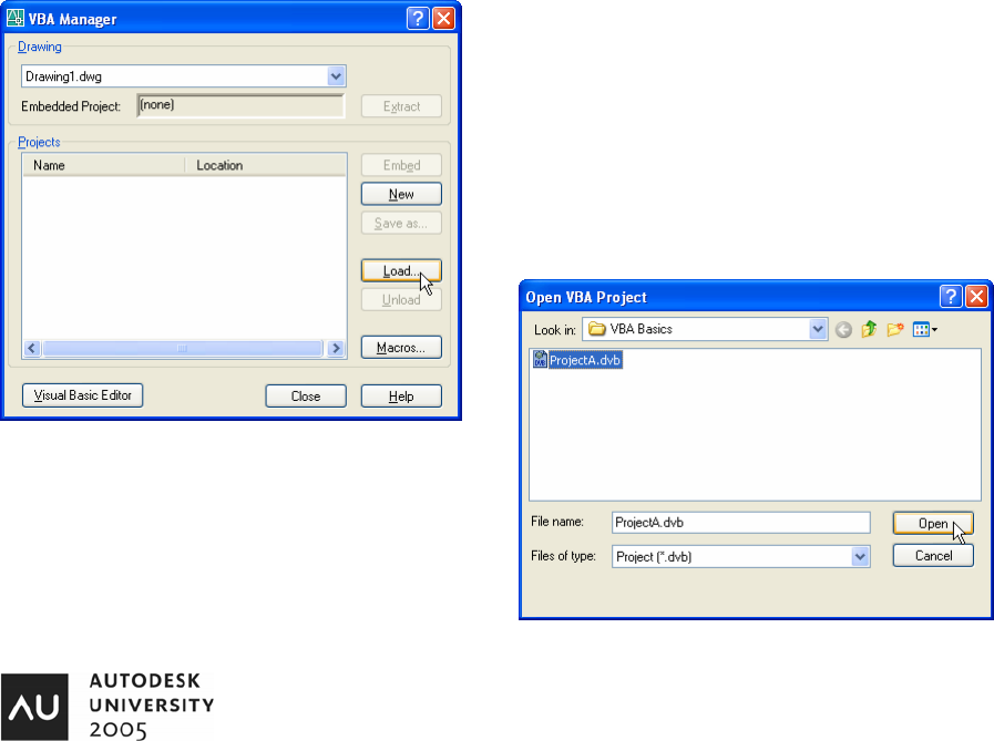
The VBA Manager can be displayed by using the menu: Tools >
Macro > VBA Manager or by typing “vbaman” at the Command
Line.
With the VBA Manager displayed, click the “Load” button.
Under the VBA Basics folder, select “ProjectA” and click the
Open button.
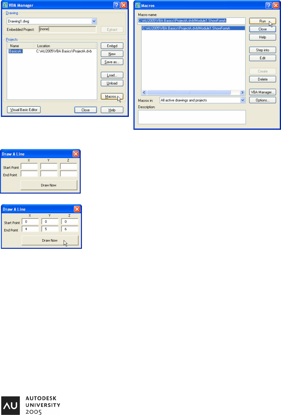
We are returned back to the VBA Manager. Now, select the
Project in the VBA Manager and click the Macros Button.
VBA: Hands-On Introduction to VBA Programming
3
Select the macro “ShowFormA” from the list and click “Run”.
This is the User Form that is displayed by the macro “ShowFormA”. Six Text
Boxes, five Labels, and a Command Button are used in this Form. Let’s use the
Form by entering values for a line’s Start Point and End Point.
Entering values of (0, 0, 0) and (4, 5, 6) and clicking the “Draw Now” button
results in a line created with the entered start and end points.
After the line is drawn, click the red “X” in the upper-right hand corner of the Form
to close the Form.
Let’s take a look at the code behind the Form. To do this, we need to enter the VBA Environment. There are
several ways this can be done.
• Click the “Visual Basic Editor” button in the VBA Manager.
• AutoCAD Menu: Tools > Macro > Visual Basic Editor
• Command Line: “vbaide”
• Shortcut Key: Alt + F11
Using any of these methods opens the Visual Basic Editor.
VBA: Hands-On Introduction to VBA Programming
4
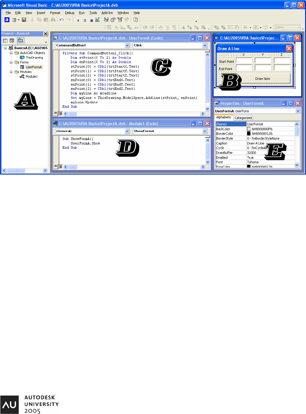
This is the VBA Development Environment. Five areas are shown with labels A through E.
A. The VBA Project Window
B. User Form named “UserFormA”
C. The Code behind “UserFormA”
D. Code Module named “Module1”
E. Properties Window (currently showing “UserFormA”)
Let’s follow the flow of the macro “ShowFormA”.
1. Show the Form named “UserFormA”
2. UserFormA is displayed and waits for user interaction.
3. The Button with a Caption of “Draw Now” is named “CommandButton1”. When the user clicks the button,
the following things take place:
a. Two variables are Declared. The variables are named “stPoint” and “enPoint”. These variables
are declared as a Double, which means a very precise number. These variables are declared as
Arrays. Each variable array has three components (0, 1, and 2).
b. We begin getting the values that had been entered in the Form and place them in the X, Y, and Z
(0, 1, and 2) elements of the arrays. The values are entered in Text Boxes so we convert the
values to Doubles by using the CDbl Function.
c. We declare a variable “myLine” as an AcadLine Object.
d. We add the Line to ModelSpace.
e. We Update the Line which refreshes the line in the AutoCAD editor window.
VBA: Hands-On Introduction to VBA Programming
5
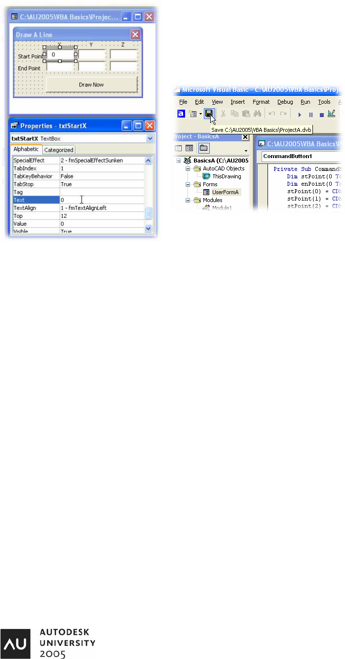
Let’s make a modification to the Form by entering (0, 0, 0) and (4, 5, 6) as
the Start and End Point default values. We do this by selecting a Text Box
in the Form and changing the Text Property.
After this change is made, Save the VBA Project by clicking the Save
Button in VBA.
Executing a VBA Macro from within the VBA Editor
We have already run the Macro “ShowFormA” by selecting it from a list of Macros (see page 3). There are other
ways to run a macro.
1. Place your cursor inside the Procedure “ShowFormA”.
2. Press the F5 key on your keyboard.
3. The Macro is executed.
4. Draw a Line and then close down the Form.
Let’s take a look at another way we can “run” a macro. We are going to Step through our code.
1. Place your cursor inside the Procedure “ShowFormA”.
2. Click the F8 key on your keyboard.
3. This begins stepping through the Procedure “ShowFormA”. Each executable line is highlighted in Yellow
as we step through the code. Once the User Form is shown, enter values for the Start Point and End
Point and click the “Draw Now” button.
4. We are taken into the Click Event of “CommandButton1”.
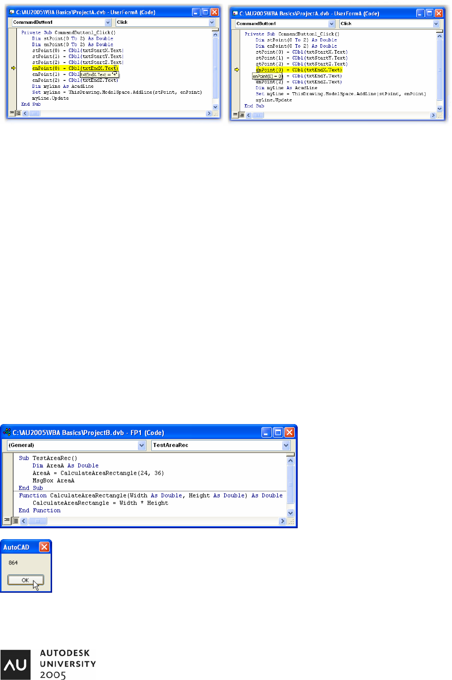
5. Continue pressing F8 until we get to the line of code where we set the value of EnPoint(0).
6. Hold your cursor over the variables and TextBox Properties. What happens?
VBA: Hands-On Introduction to VBA Programming
6
As we hold our cursor over variables and properties, we are shown their values. At this point, the value for the
variable “enPoint(0)” has not been set but we can see that it is about to be given a value of 4. Pressing the F8
key will execute the line that is highlighted and the variable “enPoint(0)” receives it’s value from the Text Box
named “txtEndX”.
Pressing F5 or hitting the Run Button in VBA will complete executing the code and a new line is added to
ModelSpace.
VBA Procedures and Functions
Let’s unload “ProjectA.dvb” and open a different VBA Project. This is done by using the VBA Manager (page 2).
1. Open the VBA Manager
2. Select “ProjectA.dvb” in the Projects List.
3. Click the “Unload” button.
4. Click the “Load” button.
5. Select “ProjectB.dvb”.
6. Click the “Visual Basic Editor” button.
7. We are now in the VBA Editor.
We will begin by looking at the Code Module “FP1”.
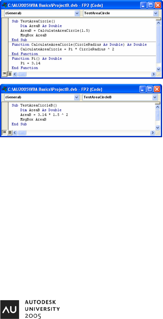
The Code Module “FP1” contains a
Procedure named “TestAreaRec” and a
Function named “CalculateAreaRectangle”.
Place your cursor in “TestAreaRec” and hit
the F5 button on your keyboard. What do
you see?
After hitting the “OK” button, let’s step through the execution of the Procedure “TestAreaRec”.
Remember, this is done by clicking the F8 button on the keyboard.
VBA: Hands-On Introduction to VBA Programming
7
Several principles are demonstrated in this example.
• Functions are used to return values (and Objects).
• Parameters for Functions and Procedures are placed between the parenthesis that follow the Name of the Function or
Procedure.
• Return values for Functions are set by assigning a value to the name of the Function. In this example, the Function is
named “CalculateAreaRectangle” so we use “CalculateAreaRectangle = Width * Height”.
• Code execution can jump from one Procedure or Function to another but returns to the calling Procedure or Function
after execution is complete.
Let’s take a look at the Code Module “FP2”.
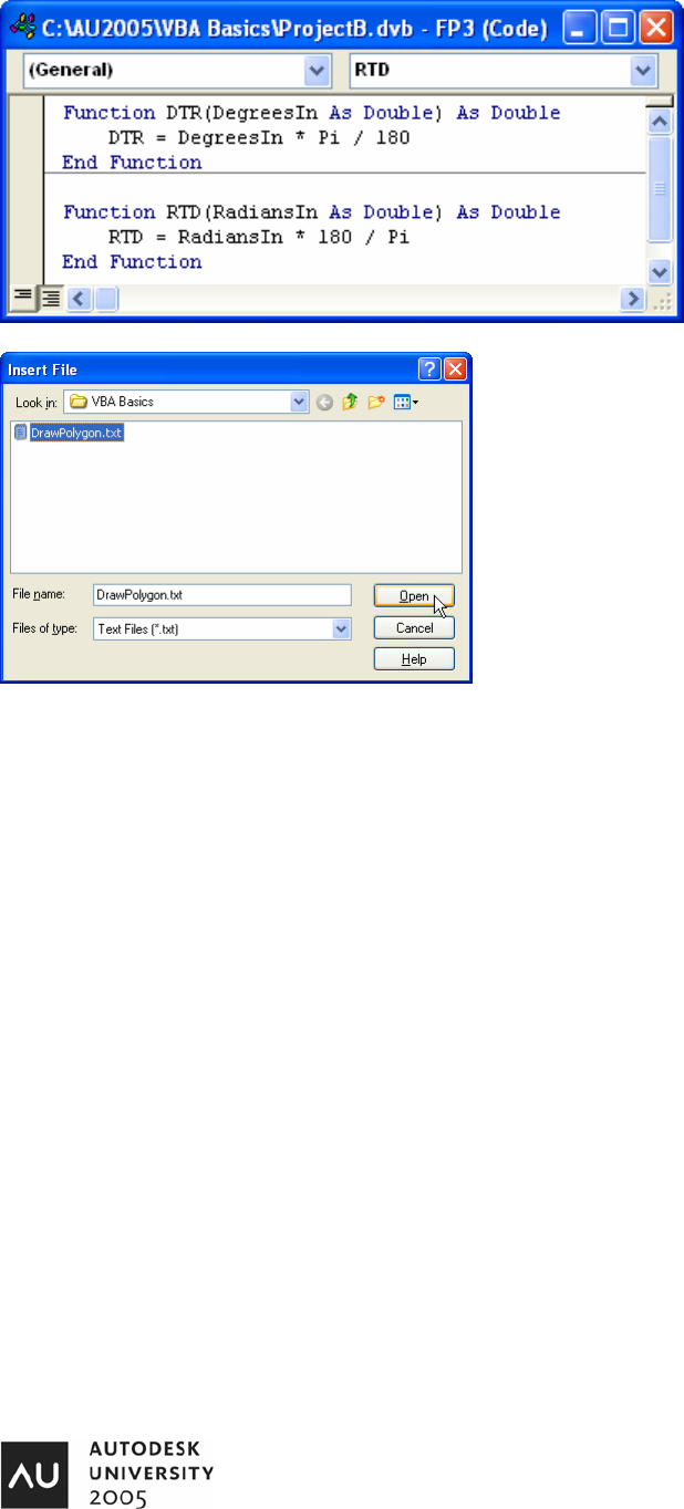
“FP2” contains one Procedure and two Functions. Follow
the code execution by looking at the screen capture shown
here. Begin with “TestAreaCircle” and number the lines as
they will be executed. Keep in mind that Variable
Declarations are not executable.
Take a look at the Function “Pi”. This function returns a
value for Pi so we do not need to hard-code the value, we
can just use the Pi function.
What do we have here? Running the Procedure
“TestAreaCircleB” provides the same results as running
“TestAreaCircle”. It does so without the use of any other
Functions or Procedures. So, why would we divide up our
code when we can have it all in one Procedure?
Any time a section of code can be broken out into it’s own Function or Procedure, it should be looked at very carefully. Consider
the Pi function. Today, it’s value is 3.14. What if we decide 2 months from now that we need a more accurate number? If we
do not use a function, we may find that number in 100 different places. We would need to replace 3.14 with 3.14159 in 100
different places. If we had used a Function (as we are in FP2), we would only have to make a change in one place. And if
tomorrow we decide we need more accuracy than 3.14159, we could use the line of code:
Pi = Atn(1) * 4
Let’s make that change right now. In the Pi Function, change the code from “Pi = 3.14” to “Pi = Atn(1) * 4”. This calculation will
return a very precise value for Pi.
Parameters in Functions and Procedures
Some Functions and Procedures make use of Parameters. These are variables that get passed into the Function or Procedure
that make the Function or Procedure dynamic – the results are based on the Parameter. For example, the
“CalculateAreaRectangle” Function. This Function has two parameters, the Width and Height.
Open the Code Module “FP3” in the active project. We will begin by typing in two Functions. DTR (Degrees to Radians) and
RTD (Radians to Degrees).
VBA: Hands-On Introduction to VBA Programming
8
Here are our two Functions. As the code is
typed in, pay particular attention to what is
happening as you type the code. VBA is
attempting to help us by showing us possible
variable types and other things.
Now, we are going to Import some code. Place your cursor after the
RTD function. Then go to the VBA menu: Insert > File. Select the file
“DrawPolygon.txt” and click the “Open” button.
This inserts the code inside the “DrawPolygon.txt” file into our Code
Module. Here is the code:
Sub DrawPolygon()
Dim NumOfSides As Long
Dim I As Long
Dim tmpPoint As Variant
Dim PolyRadius As Double
Dim CenPt(0 To 2) As Double
Dim myPoly As Acad3DPolyline
Dim PGPoints() As Double
NumOfSides = 3
ReDim PGPoints(0 To NumOfSides * 3 - 1) As Double
CenPt(0) = 0: CenPt(1) = 0: CenPt(2) = 0
PolyRadius = 3
For I = 1 To NumOfSides
tmpPoint = ThisDrawing.Utility.PolarPoint(CenPt, _
DTR((360 / NumOfSides) * (I - 1)), PolyRadius)
PGPoints((I - 1) * 3 + 0) = tmpPoint(0)
PGPoints((I - 1) * 3 + 1) = tmpPoint(1)
PGPoints((I - 1) * 3 + 2) = tmpPoint(2)
Next I
Set myPoly = ThisDrawing.ModelSpace.Add3DPoly(PGPoints)
myPoly.Closed = True
End Sub
This Procedure makes use of the DTR (Degrees to Radians) function. As we can see, variables are used for the Number of
Sides, Center Point, and Radius. Let’s import another Text File named “DrawPolygon2”.
VBA: Hands-On Introduction to VBA Programming
9
Sub TestDrawPGon2()
DrawPolygon2 0, 0, 0, 12, 4
End Sub
Sub DrawPolygon2(X As Double, Y As Double, Z As Double, _
NumOfSides As Long, PolyRadius As Double)
Dim I As Long
Dim tmpPoint As Variant
Dim CenPt(0 To 2) As Double
Dim myPoly As Acad3DPolyline
Dim PGPoints() As Double
ReDim PGPoints(0 To NumOfSides * 3 - 1) As Double
CenPt(0) = X: CenPt(1) = Y: CenPt(2) = Z
For I = 1 To NumOfSides
tmpPoint = ThisDrawing.Utility.PolarPoint(CenPt, _
DTR((360 / NumOfSides) * (I - 1)), PolyRadius)
PGPoints((I - 1) * 3 + 0) = tmpPoint(0)
PGPoints((I - 1) * 3 + 1) = tmpPoint(1)
PGPoints((I - 1) * 3 + 2) = tmpPoint(2)
Next I
Set myPoly = ThisDrawing.ModelSpace.Add3DPoly(PGPoints)
myPoly.Closed = True
End Sub
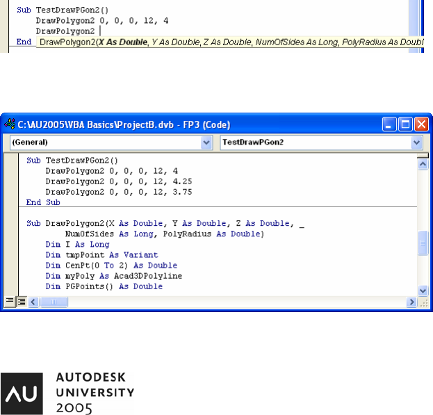
The Text File “DrawPolygon2” has two procedures in it. One is “DrawPolygon2” and the other is “TestDrawPGon2”.
DrawPolygon2 can not be run by itself. It requires something else to call it and to supply the parameters. With your cursor
inside “TestDrawPGon2”, hit the F5 button on your keyboard. Switching to AutoCAD shows us that the code works. Now, let’s
try adding a few more polygons to the TestDrawPGon2 Procedure. As we add lines of code, VBA helps us to know what it is
expecting.
When we hit the Space bar after typing “DrawPolygon2”, VBA displays the parameters for us so we know what to type in. We
begin with the X, Y, and Z values for the Center point of the Polygon. Next, we enter the number of sides. Last, we enter the
Radius of the Polygon. Let’s enter several additional lines of code as follows:
You can copy and paste the code or you can
type it in. Whatever you are most comfortable
with is fine.

VBA: Hands-On Introduction to VBA Programming
10
Function and Procedure Review
A Function or Procedure is a group of code that is given a name. Functions and Procedures can be passed
Parameters. A Parameter is a variable declared as part of a Function or Procedure and a Parameter is normally
used inside the Function or Procedure.
Drawing AutoCAD Entities
We have already drawn a few AutoCAD Entities. We have drawn Lines and 3dPolyLines. Let’s look at some simple examples
that draw in AutoCAD.
Using the VBA Manager, Unload the Project “ProjectB” and Load the Project “ProjectC”. We will be looking at “Module1”. It
contains four Procedures named “DrawALine”, “DrawACircle”, “DrawAnArc” and “DrawText”. Two Functions are also included.
Sub DrawALine()
Dim StPoint(0 To 2) As Double
Dim EnPoint(0 To 2) As Double
Dim myLine As AcadLine
Dim myColor As New AcadAcCmColor
StPoint(0) = 0: StPoint(1) = 0: StPoint(2) = 0
EnPoint(0) = 4: EnPoint(1) = 5: EnPoint(2) = 6
Set myLine = ThisDrawing.ModelSpace.AddLine(StPoint, EnPoint)
myColor.SetRGB 255, 0, 0
myLine.TrueColor = myColor
End Sub
Sub DrawACircle()
Dim CenPt(0 To 2) As Double
Dim myCircle As AcadCircle
Dim CirRad As Double
CirRad = 3
Set myCircle = ThisDrawing.ModelSpace.AddCircle(CenPt, CirRad)
myCircle.Layer = "Circles"
End Sub
Sub DrawAnArc()
Dim CenPt(0 To 2) As Double
Dim ArcRad As Double
Dim StAngle As Double
Dim EnAngle As Double
Dim myArc As AcadArc
ArcRad = 3.25
StAngle = DTR(45)
EnAngle = DTR(135)
Set myArc = ThisDrawing.ModelSpace.AddArc(CenPt, ArcRad, StAngle, EnAngle)
myArc.Lineweight = acLnWt090
End Sub
Sub DrawText()
Dim InsPoint(0 To 2) As Double
Dim TextToEnter As String
Dim TextSize As Double
Dim myText As AcadText
TextToEnter = InputBox("Text to enter:")
TextSize = 0.25
Set myText = ThisDrawing.ModelSpace.AddText(TextToEnter, InsPoint, TextSize)
End Sub
Function DTR(DegreesIn As Double) As Double
DTR = DegreesIn * Pi / 180
End Function
Function Pi() As Double
Pi = Atn(1) * 4
End Function
VBA: Hands-On Introduction to VBA Programming
11
Feel free to run any of the Procedures by hitting the F5 key or by stepping through the code with the F8 key. Remember, the
cursor must be in the Procedure you want to run. Otherwise, you may be prompted to select which Procedure you are wanting
to run. As you can see, drawing in AutoCAD with VBA is very easy. In most cases, VBA in AutoCAD only asks for the most
basic information in order to create a new AutoCAD entity. A line can be defined by two points. A circle can be defined by a
center point and a radius. An Arc is created with a Center Point, a Radius, a Start Angle, and an End Angle. Text is created
with a TextString, an Insertion Point and a Text Height.
If an entity is created as shown above, we can use the variable pointing to the entity to set the entity’s properties. In the above
example, we are setting a line’s Color, a circle’s Layer, and an arc’s Lineweight.
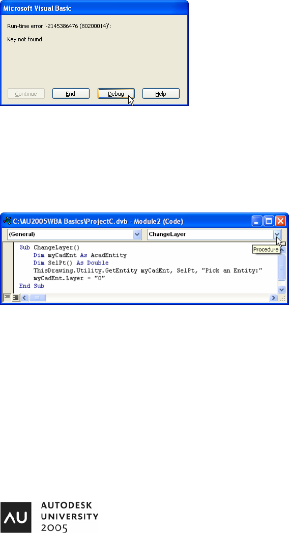
In the DrawACircle example, you may see this error:
If you hit the “Debug” button, you will be taken to the line of code that is causing
the error. You will find that the code is attempting to set the Circle’s Layer to
“Circles”. This error is telling us that the current drawing does not have a Layer
named “Circles”. Since error handling is outside the scope of this class, we will
resolve the issue by creating a new Layer named “Circles”.
Modifying AutoCAD Entities
We have already seen how we can change a new entity’s Layer by setting the Layer property. We did this when we created a
new Circle. We can modify existing AutoCAD entities as well. We just need to know which entity to modify and how it is to be
modified. Let’s take a look at Module2. We will begin with the Procedure “ChangeLayer”.
In the lower-left hand corner of the Code Module
window, two buttons are shown. One restricts our
view to a single Procedure or Function and the other
opens our view to all Procedures/Functions in the
Module. Let’s select the Procedure View.
The Procedure Combo Box shows us all Procedures
in the Module. This allows us to switch from
Procedure to Procedure very quickly.
“ChangeLayer” allows the user to select an entity in AutoCAD. The selected entity’s Layer is set to “0”. Only a few lines of code
are required to begin making simple changes to existing geometry.
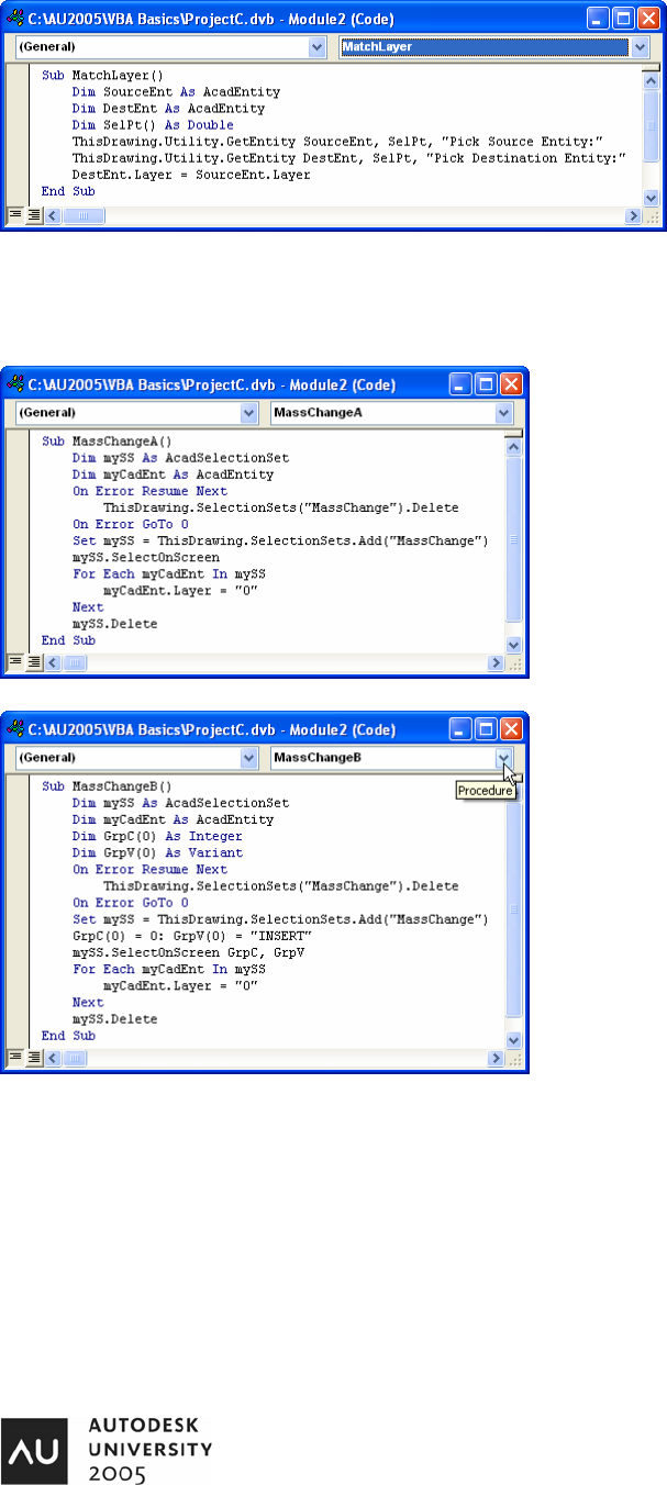
Now, in the Procedure Combo Box (Upper-right hand corner of the Code Module), select “MatchLayer”.
VBA: Hands-On Introduction to VBA Programming
12
This is a common macro. It allows the user to
select a Source Entity and a Destination Entity.
The Destination Entity’s Layer is changed to
match the Source Entity’s Layer. Once again,
only a few lines of code are required.
If it looks like the Procedure is locked up, it is
probably because AutoCAD is waiting for you to
select an Entity. You must switch to the
AutoCAD Window to do this.
Selecting individual Entities may be just what needs to be done for some macros. But if we need to select multiple entities, we
need to move to using Selection Sets. Let’s change to the Procedure “MassChange” by selecting it from the Procedures
Combo Box.
MassChangeA uses a Selection Set named “MassChange”. It
is not uncommon for Selection Sets to be left inside AutoCAD
drawings. For this reason, one of the first things we do is to
attempt to delete a selection set named “MassChange”. If it
does not exist, an error would normally appear. But because we
use “On Error Resume Next”, we continue executing code even
if there is an error. “On Error GoTo 0” (that is a zero at the end)
tells VBA to handle errors normally from that point on.
We allow the user to select entities on-screen and we change
the Layer of each entity in the Selection Set to “0”.
Further refinement in Selection Set use can be seen in
“MassChangeB”. In this example, we are filtering our Selection
Set to only allow the selection of Blocks (AKA: Insert).
Try running the code and see how only Blocks can be selected.
To restrict selection to only Lines, change “INSERT” to “LINE”.
“CIRCLE”, “ARC” and “TEXT” are a few of the other entity types
that can be filtered when working with Selection Sets.
VBA: Hands-On Introduction to VBA Programming
13
Block Attribute Extraction
We saw how we could ask the user to select an entity a couple of minutes ago. After selecting an entity, we can get and set it’s
properties. When we work with Attributes, we Get the Attributes and then address each attribute one by one.
Unload “ProjectC” and Load “ProjectD” into VBA.
Next, open the file “C:\Program Files\AutoCAD 2006\Sample\Blocks and Tables – Imperial.dwg”. After the file is open, switch to
the “Model” Layout (ModelSpace).
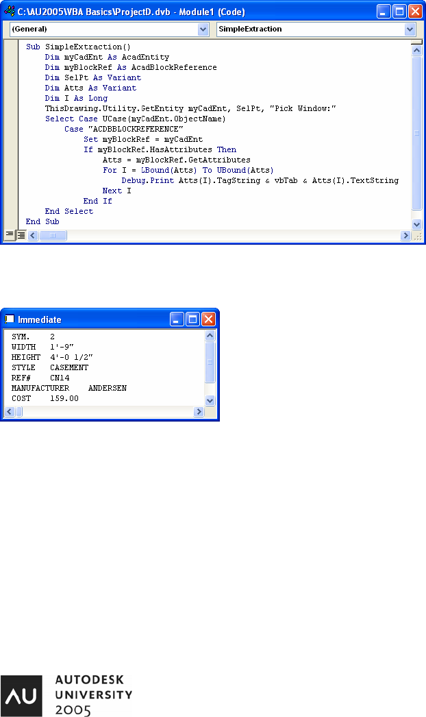
Now, let’s look at the Procedure “SimpleExtraction”.
We ask the user to Pick a Window. But we
can not restrict the user’s selection when using
GetEntity so we look at it to see what type of
entity was selected. If the user selected an
“ACDBBLOCKREFERENCE”, we set a
variable declared as an AcadBlockReference
to the selection.
Now, we know the user selected a Block. But
does the block have any attributes? If the
HasAttributes property is True, we Get the
Attributes and then look at each one by using
a For . . . Next loop.
You will see “Debug.Print” statements from
time to time. This is asking VBA to Print
something to the Debug Window. The Debug Window is also known as the Immediate Window. Visibility of the Immediate
Window can be toggled by going to the VBA Menu: View > Immediate Window. After selecting a Window Block in the “Blocks
and Tables” file, the Immediate Window should look something like this:
We can see each Attribute Tag and it’s associated Attribute TextString (value of the
attribute) displayed here. But what good is the Immediate Window? We can’t do
much with it. Right? OK. Let’s output our attributes to an ASCII Text File.
VBA: Hands-On Introduction to VBA Programming
14
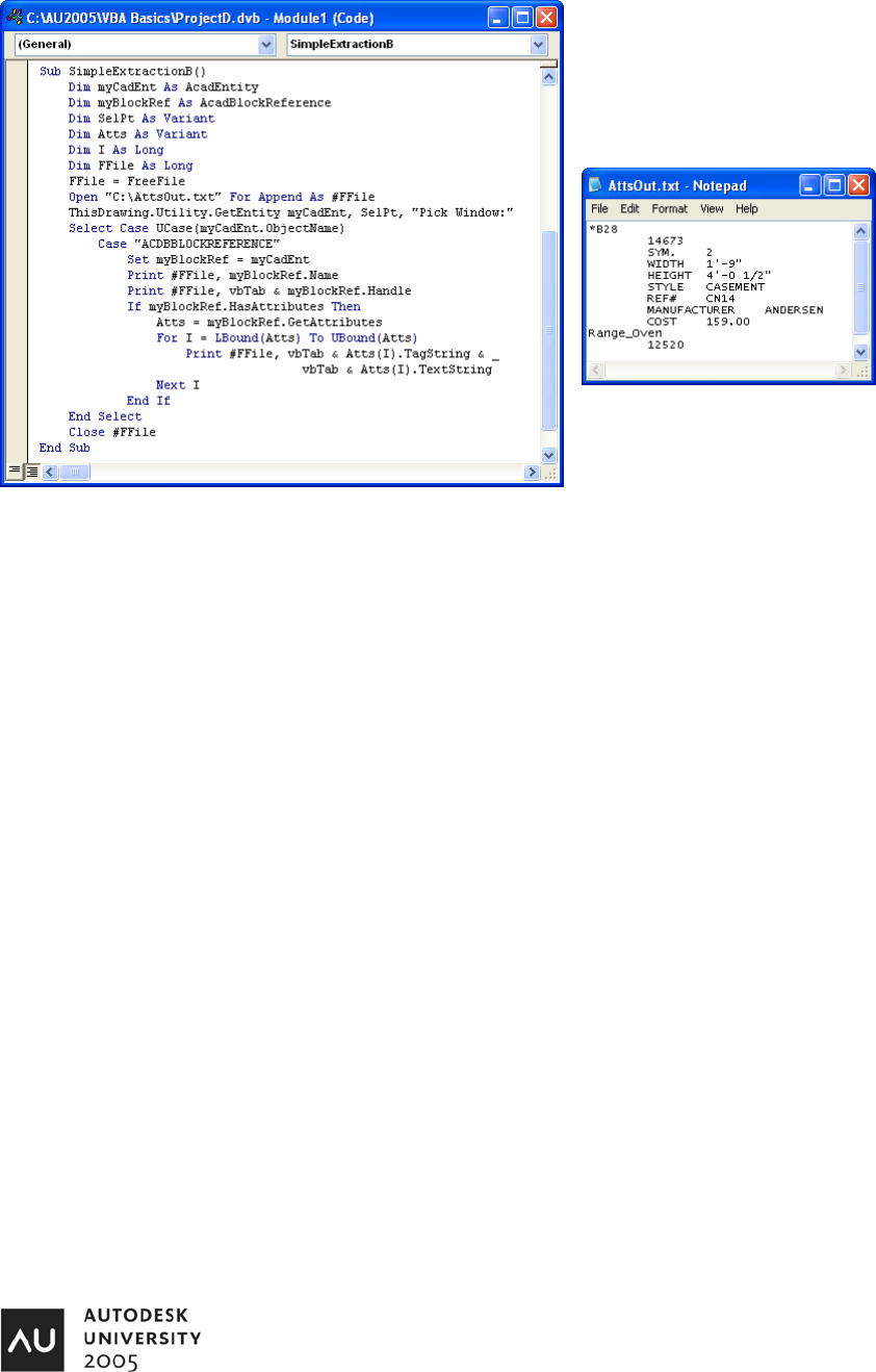
Select “SimpleExtractionB” from the Procedures Combo Box.
Now, instead of printing to the Debug window, we are
Printing to a file on the hard drive. The path of the file is
“C:\AttsOut.txt”. It is appended each time the macro is
run. Here is a screen shot of the file after a couple of
blocks have been selected:
Attributes can be extracted to Microsoft Excel, to a database, XML file, uploaded to a Web Server,
or sent as an Instant Message to someone’s cell phone. The sky is the limit. And the great thing
is, it only takes a few more lines of code to accomplish any of these tasks.
In 2004, this class was a 3 ½ hour lab. In 2005 it has been reduced to 90 minutes. I hope the
information presented here has been helpful and you will consider looking at the other classes I am
teaching this year at Autodesk University.
I would like to extend my sincere appreciation for those assisting me in this class. This class is
being presented twice this year, so four individuals are serving you and me as Assistants.
Phil Kreiker, Nauman Mysorewala, Allen Gager, and Thomas Parks. Thank you so much for your help.
I look forward to seeing each of you at future Autodesk University events.
Thank you.
Jerry Winters
President, VB CAD, Inc.
