
Publication 1756-RM014B-EN-P - November 2023
Supersedes Publication 1756-RM014A-EN-P - March 2022
Reference Manual
Original Instructions
Logix 5000 Controllers
Import/Export
1756 ControlLogix, 1756 GuardLogix, 1769 CompactLogix,
1769 Compact GuardLogix, 1789 SoftLogix, 5069
CompactLogix, 5069 Compact GuardLogix, Studio 5000
Logix Emulate
Logix 5000 Controllers Import/Export
2 Publication 1756-RM014B-EN-P - November 2023
Important User Information
Read this document and the documents listed in the additional resources section about installation, configuration, and
operation of this equipment before you install, configure, operate, or maintain this product. Users are required to familiarize
themselves with installation and wiring instructions in addition to requirements of all applicable codes, laws, and standards.
Activities including installation, adjustments, putting into service, use, assembly, disassembly, and maintenance are required to
be carried out by suitably trained personnel in accordance with applicable code of practice.
If this equipment is used in a manner not specified by the manufacturer, the protection provided by the equipment may be
impaired.
In no event will Rockwell Automation, Inc. be responsible or liable for indirect or consequential damages resulting from the use
or application of this equipment.
The examples and diagrams in this manual are included solely for illustrative purposes. Because of the many variables and
requirements associated with any particular installation, Rockwell Automation, Inc. cannot assume responsibility or liability for
actual use based on the examples and diagrams.
No patent liability is assumed by Rockwell Automation, Inc. with respect to use of information, circuits, equipment, or software
described in this manual.
Reproduction of the contents of this manual, in whole or in part, without written permission of Rockwell Automation, Inc., is
prohibited.
Throughout this manual, when necessary, we use notes to make you aware of safety considerations.
WARNING:
Identifies information about practices or circumstances that can cause an explosion in a hazardous environment, which may lead to
personal injury or death, property damage, or economic loss.
ATTENTION:
Identifies information about practices or circumstances that can lead to personal injury or death, property damage, or economic loss.
Attentions help you identify a hazard, avoid a hazard, and recognize the consequence.
IMPORTANT
Identifies information that is critical for successful application and understanding of the product.
Labels may also be on or inside the equipment to provide specific precautions.
SHOCK HAZARD: Labels may be on or inside the equipment, for example, a drive or motor, to alert people that dangerous voltage may be present.
BURN HAZARD:
Labels may be on or inside the equipment, for example, a drive or motor, to alert people that surfaces may reach dangerous
temperatures.
ARC FLASH HAZARD:
Labels may be on or inside the equipment, for example, a motor control center, to alert people to potential Arc Flash. Arc Flash will
cause severe injury or death. Wear proper Personal Protective Equipment (PPE). Follow ALL Regulatory requirements for safe work practices and for
Personal Protective Equipment (PPE).
Rockwell Automation recognizes that some of the terms that are currently used in our industry and in this publication are not in
alignment with the movement toward inclusive language in technology. We are proactively collaborating with industry peers to
find alternatives to such terms and making changes to our products and content. Please excuse the use of such terms in our
content while we implement these changes.
Publication 1756-RM014B-EN-P - November 2023 3
Summary of changes
This manual includes new and updated information. Use these reference
tables to locate changed information.
Grammatical and editorial style changes are not included in this summary.
Global changes
This table identifies changes that apply to all information about a subject in
the manual and the reason for the change. For example, the addition of new
supported hardware, a software design change, or additional reference
material would result in changes to all of the topics that deal with that subject.
Change
Topic
Updated topic Tag attributes on page 108
Updated topic Import and export revision history introduction
on page 293
New or enhanced features
This table lists new features in this release:
• OPC UA access.
• Safety signature elements.
Change
Topic
Added a new chapter
Define safety signatures on page 271
Added new topic Export a project to an .L5X text file for projects
with OPC UA Access on page 28
Added new topic Export a project to an .L5K text file for projects
with OPC UA Access on page 27

Publication 1756-RM014B-EN-P - November 2023 5
Table of Contents
Studio 5000 environment ......................................................................... 19
Supported controllers ................................................................................20
Additional resources .................................................................................. 22
Legal Notices .............................................................................................. 22
Chapter 1
Import and export introduction ............................................................... 23
Export a project to an .L5K text file .......................................................... 23
Import an .L5K text file ............................................................................. 24
Export a project to an .L5K text file for projects with OPC UA Access ...27
Export a Project to an .L5X XML File ........................................................27
Export a project to an .L5X text file for projects with OPC UA Access .. 28
Import an .L5X XML File........................................................................... 28
Export to a .CSV or .TXT file ...................................................................... 31
Import a .CSV or .TXT file ......................................................................... 33
Export source-protected logic ................................................................... 35
Export in a Cleartext Format............................................................... 36
Maintaining controller access ................................................................... 39
.L5X file structure ...................................................................................... 40
.L5X file conventions ................................................................................. 42
L5X Internal file comments ................................................................ 42
Component Descriptions .................................................................... 43
Boolean attribute values ...................................................................... 43
Data display style.................................................................................. 43
Data formats ......................................................................................... 43
.L5K file structure ...................................................................................... 48
.L5K file conventions ..................................................................................49
L5K Internal file comments .................................................................49
Component descriptions .....................................................................49
Display style ......................................................................................... 50
Project documentation ............................................................................. 50
Chapter 2
Controller component introduction......................................................... 53
Controller component ............................................................................... 53
L5X controller structure....................................................................... 53
L5K CONTROLLER structure .............................................................. 55
Controller elements ............................................................................. 55
Controller attributes ............................................................................ 56
Controller attributes in a safety controller system ..................................58
Controller guidelines .................................................................................58
Summary of changes
Preface
Import and export files
Define a controller component

Table of Contents
6 Publication 1756-RM014B-EN-P - November 2023
Controller component examples ............................................................... 59
Chapter 3
Datatype component introduction........................................................... 67
Datatype component ................................................................................. 67
L5X datatype structure ........................................................................ 67
L5K datatype structure......................................................................... 67
Datatype elements................................................................................ 67
Datatype attributes ............................................................................. 68
Datatype member ...................................................................................... 68
L5X datatype member structure ........................................................ 68
L5K datatype member structure .........................................................69
Datatype member elements ................................................................69
Datatype member attributes ...............................................................69
Bit members ........................................................................................ 70
Datatype guidelines.................................................................................... 71
Datatype component examples ................................................................. 71
Chapter 4
Module component introduction ............................................................. 73
Module component .................................................................................... 73
L5X module structure .......................................................................... 73
L5K MODULE structure....................................................................... 74
Module elements .................................................................................. 74
Module attributes ................................................................................. 74
Module attributes in a safety controller system....................................... 77
Module connection.....................................................................................78
L5X connection structure ....................................................................78
L5K CONNECTION structure .............................................................78
Connection elements ........................................................................... 79
Module connection attributes ............................................................. 79
Module connection attributes in a safety controller system ........... 80
Module guidelines ..................................................................................... 80
Module component examples ................................................................... 81
Chapter 5
Add-On Instruction component introduction ........................................ 85
Add-On Instruction component ............................................................... 85
L5X AddOnInstructionDefinition Structure ..................................... 85
L5K ADD_ON_INSTRUCTION_DEFINITION structure ................. 86
Add-On Instruction elements ............................................................ 86
Add-On Instruction attributes ............................................................87
Define a Datatype component
Define a module component
Define an Add-On Instruction
component

Table of Contents
Publication 1756-RM014B-EN-P - November 2023 7
Routines in Add-On Instructions .......................................................87
Parameters ................................................................................................. 88
L5X parameters structure ................................................................... 88
L5K parameters structure ................................................................... 89
Parameter elements ............................................................................ 90
Parameters attributes .......................................................................... 91
Signature history ....................................................................................... 92
L5X SignatureHistory structure ........................................................ 92
L5K HISTORY_ENTRY structure ........................................................ 93
History entry attributes ....................................................................... 93
Local tags ..................................................................................................... 93
L5X LocalTags structure ...................................................................... 93
L5K LOCAL_TAGS structure ................................................................94
Local tag attributes...............................................................................94
Encoded/Unencoded Add-On Instructions ............................................. 95
L5X EncodedData Structure................................................................ 95
L5K ENCODED_DATA Structure........................................................ 95
Encoded data attributes ...................................................................... 95
Encoded Information elements ..........................................................96
Encoded key attributes ........................................................................96
Encoded content attributes .................................................................96
L5X Encoded Add-On Instruction example ....................................... 97
L5K Encoded Add-On Instruction example ....................................... 97
Add-On Instruction Guidelines................................................................ 98
L5X unencoded AddOnInstruction definition example .................. 98
L5K unencoded ADD_ON_INSTRUCTION _DEFINITION example
............................................................................................................ 100
L5X unencoded safety AddOnInstruction definition example ...... 102
L5K unencoded safety ADD_ON_INSTRUCTION _DEFINITION
example ............................................................................................... 102
Chapter 6
Tag component introduction .................................................................. 105
Tag component ........................................................................................ 105
L5X tag structure ................................................................................ 105
L5K TAG structure .............................................................................. 106
Tag elements ....................................................................................... 106
Tag attributes .....................................................................................108
Produced tag attributes ..................................................................... 110
Consumed tag attributes ................................................................... 110
ALARM_ANALOG tag ............................................................................... 110
L5X tag structure for ALARM_ANALOG tag ..................................... 111
Define a tag component

Table of Contents
8 Publication 1756-RM014B-EN-P - November 2023
L5K tag structure for ALARM_ANALOG tag ..................................... 111
ALARM_ANALOG tag attributes ........................................................ 111
ALARM_DIGITAL tag ................................................................................ 113
L5X tag structure for ALARM_DIGITAL tag ..................................... 113
L5K tag structure for an ALARM_DIGITAL tag ................................ 113
ALARM_DIGITAL tag attributes ........................................................ 113
L5X AlarmConfig structure ......................................................................114
AlarmConfig elements ........................................................................115
L5K ANALOG_ALARM message structure ........................................115
ALMMSG elements .............................................................................115
MESSAGE tag ............................................................................................115
L5X message structure ....................................................................... 116
L5K MESSAGE structure ................................................................... 116
Message tag attributes ....................................................................... 116
AXIS_CIP_DRIVE, AXIS_CONSUMED, AXIS_GENERIC_DRIVE,
AXIS_SERVO, AXIS_SERVO_DRIVE, or AXIS_VIRTUAL Tag..............117
L5X axis structure ...............................................................................117
L5K AXIS TAG structure .....................................................................117
Axis tag attributes ...............................................................................117
COORDINATE_SYSTEM tag ................................................................... 128
L5X CoordinateSystem structure ..................................................... 128
L5K COORDINATE_SYSTEM structure ........................................... 129
Coordinate system tag attributes ..................................................... 129
MOTION_GROUP Tag ............................................................................. 130
L5X MotionGroup structure .............................................................. 130
L5K MOTION_GROUP structure ...................................................... 130
Motion Group Tag attributes ............................................................ 130
HMIBC tag ................................................................................................. 131
L5X HMIBC structure ......................................................................... 131
L5K HMIBC structure ......................................................................... 131
HMIBC attributes ............................................................................... 131
SAFETY tag................................................................................................. 131
L5X safety structure ............................................................................ 131
L5K SAFETY structure ........................................................................ 132
Safety tag attributes ........................................................................... 132
Tag initial values ....................................................................................... 132
L5X initial tag value............................................................................ 133
L5K initial TAG value .......................................................................... 133
Add-On Instruction tag values .......................................................... 133
Add-On Instruction tag values example ........................................... 134
Tag guidelines ........................................................................................... 134
Tag initial values examples ...................................................................... 135

Table of Contents
Publication 1756-RM014B-EN-P - November 2023 9
Chapter 7
Tag-based alarms introduction ............................................................... 141
Tag-based alarms ...................................................................................... 141
L5X Tag-based alarm structure .......................................................... 141
L5K Tag-based alarm structure ......................................................... 142
Tag-based alarm objects .................................................................... 145
Tag-based alarm definitions.................................................................... 148
L5X Tag-based alarm definition structure ....................................... 149
L5K Tag-based alarm definition structure ....................................... 150
Tag-based alarm definition objects .................................................. 150
Chapter 8
Program component introduction .......................................................... 153
Program component ................................................................................. 153
L5X program structure ...................................................................... 153
Program elements .............................................................................. 154
Program attributes ............................................................................. 154
Program attributes for EquipmentPhase programs ....................... 155
Program attributes for Sequence programs .................................... 156
Child program component ...................................................................... 156
L5K CHILD_PROGRAM structure .................................................... 156
L5X child program structure ............................................................. 157
Child program attributes ................................................................... 157
Child program guidelines .................................................................. 157
Encoded/Unencoded routines ................................................................ 157
L5X EncodedData Structure.............................................................. 157
L5K ENCODED_DATA Structure...................................................... 158
Encoded Data Elements .................................................................... 158
Encoded Information elements ........................................................ 158
Encoded key attributes ...................................................................... 158
Encoded content attributes ............................................................... 159
L5K source protected routine example ............................................. 159
L5X source-protected routine example ............................................ 159
Program guidelines .................................................................................. 159
Program guidelines examples ................................................................. 160
Chapter 9
Ladder logic routine introduction ........................................................... 163
Ladder logic routine.................................................................................. 163
L5X ladder logic routine structure .................................................... 163
L5K Ladder Logic ROUTINE structure ............................................. 163
Ladder logic routine elements........................................................... 163
Define a tag-based alarm or
alarm definition
Define a program component
Define a ladder logic routine

Table of Contents
10 Publication 1756-RM014B-EN-P - November 2023
RLL Routine attributes ...................................................................... 164
Rung logic ................................................................................................. 164
L5X rung structure ............................................................................. 164
L5K RUNG structure .......................................................................... 164
Rung elements .................................................................................... 165
Rung attributes .................................................................................. 165
Rung guidelines ........................................................................................ 165
Single or simultaneous branches ............................................................ 165
L5X branch structure ......................................................................... 166
L5K BRANCH structure ..................................................................... 166
L5X Examples ........................................................................................... 166
L5K examples ............................................................................................ 167
Neutral text for ladder instructions ........................................................ 167
Chapter 10
Function block diagram routine introduction ....................................... 175
Function BlockDiagram Routine ............................................................. 175
L5X function block diagram routine structure ................................. 175
L5K Function Block FBD_ROUTINE structure ................................ 175
Function block routine elements ...................................................... 176
FBD_routine attributes...................................................................... 176
Sheet .......................................................................................................... 176
L5X sheet structure ............................................................................ 176
L5K SHEET structure ......................................................................... 177
Sheet elements ................................................................................... 177
Sheet attributes .................................................................................. 178
Sheet guidelines ................................................................................. 178
Export function block logic while editing online ................................... 179
Input and output references ...................................................................180
L5X IREF and OREF structure ..........................................................180
L5K IREF and OREF structure ..........................................................180
Reference attributes ...........................................................................180
Reference guidelines .......................................................................... 181
Input and output connectors .................................................................. 181
L5X ICON and OCON structure ........................................................ 181
L5K ICON and OCON structure ........................................................ 181
Connector attributes .......................................................................... 181
Connector guidelines ......................................................................... 181
Blocks ........................................................................................................ 182
L5X block structure ............................................................................ 182
L5K BLOCK structure ......................................................................... 182
Block attributes .................................................................................. 182
Define a function block diagram
routine

Table of Contents
Publication 1756-RM014B-EN-P - November 2023 11
Block guidelines ................................................................................. 183
Functions .................................................................................................. 183
L5X function structure....................................................................... 183
L5K FUNCTION structure ................................................................. 183
Function attributes ............................................................................ 183
Add-On instructions ................................................................................ 184
L5X Add-On Instruction structure ................................................... 184
L5K ADD_ON_INSTRUCTION structure ......................................... 184
Add-On Instruction Attributes ......................................................... 184
Add-On Instruction Guidelines ........................................................ 185
JSR ............................................................................................................. 185
L5X JSR structure ............................................................................... 185
L5K JSR structure ............................................................................... 185
JSR attributes...................................................................................... 185
JSR guidelines ..................................................................................... 186
SBR ............................................................................................................ 186
L5X SBR structure .............................................................................. 186
L5K SBR structure .............................................................................. 186
SBR attributes .................................................................................... 186
SBR guidelines.................................................................................... 187
RET ............................................................................................................ 187
L5X RET structure .............................................................................. 187
L5K RET structure .............................................................................. 187
RET attributes .................................................................................... 187
RET guidelines ................................................................................... 188
Wires and feedback wires ........................................................................ 188
L5X wire structure .............................................................................. 188
L5K WIRE structure ........................................................................... 188
Wire attributes ................................................................................... 188
Wire guidelines .................................................................................. 188
Text boxes.................................................................................................. 189
L5X TextBox structure ....................................................................... 189
L5K TEXTBOX structure.................................................................... 189
Text box attributes ............................................................................. 189
Text box guidelines for block sections .............................................. 189
Function block attachments .................................................................... 189
L5X attachment structure.................................................................. 190
L5K ATTACHMENT structure ........................................................... 190
Attachment attributes........................................................................ 190
FBD element attachment guidelines ................................................ 190
Attachments examples ............................................................................. 190
Parameters for function block instructions ........................................... 194

Table of Contents
12 Publication 1756-RM014B-EN-P - November 2023
Chapter 11
Sequential function chart routine introduction ....................................199
Sequential function chart routine ...........................................................199
L5X sequential function chart structure ...........................................199
L5K sequential function chart SFC_ROUTINE structure .............. 200
Sequential function chart elements................................................. 200
SFC_Routine attributes .................................................................... 200
Export sequential function chart logic while editing online ................ 201
Steps ......................................................................................................... 203
SFC L5X step structure ..................................................................... 203
SFC L5K STEP structure ................................................................... 203
Step elements .................................................................................... 203
SFC step attributes ............................................................................ 204
Preset ........................................................................................................ 204
L5X preset structure .......................................................................... 204
L5K PRESET structure ...................................................................... 204
Limit high ................................................................................................. 205
L5X limit high structure ................................................................... 205
L5K LIMITHIGH structure ............................................................... 205
Limit low .................................................................................................. 205
L5X limit low structure ..................................................................... 205
L5K LIMITHIGH structure ............................................................... 205
Action list ................................................................................................. 206
L5X Action structure ......................................................................... 206
L5K ACTION structure ...................................................................... 206
Action attributes................................................................................ 206
Transitions ............................................................................................... 207
L5X transition structure ................................................................... 207
L5K TRANSITION structure ............................................................. 207
Transition elements .......................................................................... 207
Transition attributes ......................................................................... 207
Condition ................................................................................................. 208
L5X condition structure .................................................................... 208
L5K CONDITION structure .............................................................. 208
Subroutine calls ....................................................................................... 208
L5X SbrRet structure......................................................................... 208
L5K SBR_RET structure .................................................................... 209
Subroutine attributes ....................................................................... 209
Stops ......................................................................................................... 209
L5X stop structure ............................................................................. 209
L5K STOP structure ........................................................................... 209
Stop attributes ................................................................................... 209
Define a sequential function
chart routine

Table of Contents
Publication 1756-RM014B-EN-P - November 2023 13
SFC routine branches ............................................................................... 210
L5X branch structure ......................................................................... 210
L5K BRANCH structure ..................................................................... 210
Branch attributes ............................................................................... 210
Leg attributes ...................................................................................... 210
SFC directed links..................................................................................... 211
L5X DirectedLink structure ............................................................... 211
L5K DIRECTED_LINK structure ...................................................... 211
Directed link attributes ..................................................................... 211
Directed link guidelines..................................................................... 211
Text boxes.................................................................................................. 211
L5X TextBox structure ....................................................................... 211
L5K TEXTBOX structure.................................................................... 211
Text box attributes ............................................................................. 212
Text box guidelines for directed link blocks .................................... 212
Attachments .............................................................................................. 212
L5X attachment structure.................................................................. 212
L5K ATTACHMENT structure ........................................................... 212
Attachment attributes........................................................................ 212
SFC element attachment guidelines ................................................. 213
SFC attachments examples...................................................................... 213
Chapter 12
Structured text routine introduction ..................................................... 221
Structured text routine............................................................................ 221
L5X structured text structure ............................................................ 221
L5K structured text ST_ROUTINE structure ................................... 221
Structured Text routine elements..................................................... 221
ST_Routine attributes ....................................................................... 222
Structured text logic ................................................................................ 222
Export structured text logic while editing online .................................. 223
Structured text routine examples .......................................................... 224
Structured text......................................................................................... 226
Chapter 13
Equipment Sequence routine introduction .......................................... 233
Equipment Sequence Routine ................................................................ 233
L5X Equipment Sequence structure ................................................. 233
L5K Equipment Sequence ESQ_ROUTINE structure ..................... 234
Equipment Sequence elements......................................................... 234
ESQ_Routine attributes..................................................................... 234
Steps .......................................................................................................... 235
Define a structured text routine
Define an Equipment Sequence
routine

Table of Contents
14 Publication 1756-RM014B-EN-P - November 2023
Structured text L5X step structure ................................................... 235
Structured text L5K STEP structure ................................................. 235
Structured text step attributes .......................................................... 235
Transitions ................................................................................................ 236
L5X transition structure .................................................................... 236
L5K TRANSITION structure .............................................................. 236
Transition elements ........................................................................... 236
Transition attributes .......................................................................... 237
Stops .......................................................................................................... 237
L5X stop structure .............................................................................. 237
L5K STOP structure ............................................................................ 237
Stop attributes .................................................................................... 237
Equipment Sequence routine branches .................................................238
L5X branch structure .........................................................................238
L5K BRANCH structure .....................................................................238
Branch attributes ...............................................................................238
Leg attributes ...................................................................................... 239
Equipment Sequence directed links ....................................................... 239
L5X DirectedLink structure ............................................................... 239
L5K DIRECTED_LINK structure ...................................................... 239
Directed link attributes ..................................................................... 239
Directed link guidelines..................................................................... 239
Equipment Sequence attachments ........................................................ 240
L5X attachment structure................................................................. 240
L5K ATTACHMENT structure .......................................................... 240
Attachment attributes....................................................................... 240
Equipment Sequence element attachment guidelines .................. 240
Tag configuration .................................................................................... 240
L5X tag configuration structure ...................................................... 240
L5K TAG_CONFIGURATION structure............................................ 241
Tag configuration elements .............................................................. 241
Expression component ............................................................................ 241
L5X expression structure ................................................................... 241
L5K EXPRESSION structure ............................................................. 241
Chapter 14
Task component introduction ................................................................ 243
Task component ....................................................................................... 243
L5K TASK structure ............................................................................ 243
L5X task structure .............................................................................. 243
Task elements .....................................................................................244
Task attributes ....................................................................................244
Define a task component

Table of Contents
Publication 1756-RM014B-EN-P - November 2023 15
Task guidelines .........................................................................................244
Task component examples ...................................................................... 245
Chapter 15
Parameter connection component introduction .................................. 247
Parameter connection component ......................................................... 247
L5K PARAMETER_CONNECTION structure .................................. 247
L5X ParameterConnection structure ............................................... 247
Parameter connection attributes ...................................................... 247
Parameter connection guidelines .......................................................... 248
Parameter connection component examples ....................................... 248
Chapter 16
Trend component introduction ...............................................................251
Trend component .....................................................................................251
L5X trend structure ............................................................................ 251
L5K TREND structure ........................................................................ 251
Trend elements ...................................................................................252
Trend attributes .................................................................................252
Pen declaration ......................................................................................... 254
L5X pen structure ............................................................................... 254
L5K PEN structure.............................................................................. 255
Pen elements ...................................................................................... 255
Pen attributes ..................................................................................... 255
Trend guidelines ....................................................................................... 255
Trend component examples .................................................................... 256
Chapter 17
Watch list component introduction ....................................................... 259
Quick watch list component ................................................................... 259
L5X QuickWatchList structure.......................................................... 259
L5K QUICK_WATCH structure ......................................................... 259
Quick Watch elements ....................................................................... 259
Quick Watch List attributes .............................................................. 259
Watch tag attributes ......................................................................... 260
Watch list component examples ............................................................ 260
Chapter 18
Controller configuration objects introduction ...................................... 263
Controller objects ..................................................................................... 263
L5X config structure .......................................................................... 263
Define a parameter connection
component
Define a trend component
Define a watch list component
Define controller configuration
objects

Table of Contents
16 Publication 1756-RM014B-EN-P - November 2023
L5K CONFIG structure ...................................................................... 263
Object elements .................................................................................. 263
Config attributes ................................................................................264
Controller objects examples ....................................................................266
Chapter 19
Custom properties introduction............................................................. 269
Custom properties data ........................................................................... 269
Custom properties structure .............................................................269
Custom properties elements ............................................................ 270
Custom properties attributes ........................................................... 270
Custom properties example ................................................................... 270
Chapter 20
Safety Signatures introduction ...............................................................271
Safety Signature examples ...................................................................... 272
Signature protection and authentication............................................... 279
Authentication code examples .......................................................... 279
Chapter 21
Structure tags and comments introduction .......................................... 281
Place information in a .CSV or .TXT file ................................................ 281
L5K Internal file comments ............................................................... 281
Specify a tag record .................................................................................. 281
TAG type record ................................................................................. 282
ALIAS type record.............................................................................. 282
COMMENT type record .....................................................................283
Specify a comment record .......................................................................283
Specify an alarm message record ........................................................... 284
Specify a tag record examples .................................................................285
Appendix A
Microsoft Excel and CSV file introduction ............................................ 291
Recommendations ................................................................................... 291
Logix Designer data transformations .................................................... 291
Microsoft Excel Data Transformation ................................................... 292
Appendix B
Import and export revision history introduction.................................. 293
Backward compatibility........................................................................... 293
Import/Export version 2.27 Logix Designer application version 36 .....294
Define custom properties
Define Safety Signatures
Structure Tags and Comments
in an Import/Export File
Considerations for using
Microsoft Excel to edit a .CSV
file
Import/Export revision history

Table of Contents
Publication 1756-RM014B-EN-P - November 2023 17
Import/Export version 2.22 Logix Designer application version 31 .....294
Import/Export version 2.21 Logix Designer application version 30 .....294
Import/Export version 2.20 Logix Designer application version 29 .... 295
Import/Export version 2.19 Logix Designer application version 28 ..... 295
Import/Export version 2.18 Logix Designer application version 27 ..... 295
Import/Export version 2.17 Logix Designer application version 26 ..... 295
Import/Export version 2.15 Logix Designer application version 24 ..... 295
Import/Export version 2.12 Logix Designer application version 21 .....296
Import/Export version 2.11 Logix Designer version 20 .........................296
Import/Export version 2.10 Logix Designer version 19 ......................... 297
Import/Export version 2.8 Logix Designer version 18........................... 297
Import/Export version 2.8 Logix Designer version 17 ........................... 297
Import/Export version 2.7 Logix Designer version 16 .......................... 298
Import/Export version 2.6 Logix Designer version 15 ...........................299
Import/Export version 2.4 Logix Designer version 13 ...........................299
Import/Export version 2.3 Logix Designer version 12 ...........................299
Import/Export version 2.2 Logix Designer version 11 .......................... 300
Import/Export version 2.1 Logix Designer version 10 ........................... 301
Changes to support MESSAGE tag enhancements ......................... 301
Import/Export version 2.0 Logix Designer version 9 ........................... 302
Motion changes to support the SERCOS Protocol................................ 302
MOTION_GROUP tag structure (version 1.1) .................................. 303
AXIS tag structure (version 1.1) ......................................................... 303
Import/Export version 1.1 Logix Designer version 8 ............................ 306
Index
Publication 1756-RM014B-EN-P - November 2023 19
Preface
This manual details how to import and export controller projects. You should
be familiar with how the Logix-based controller stores and processes data.
This manual is one of a set of related manuals that show common procedures
for programming and operating Logix 5000 controllers.
For a complete list of common procedures manuals, refer to the Logix 5000
Controllers Common Procedures Programming Manual, publication
1756-PM001.
The term Logix 5000 controller refers to any controller based on the Logix
5000 operating system.
Rockwell Automation recognizes that some of the terms that are currently
used in our industry and in this publication are not in alignment with the
movement toward inclusive language in technology. We are proactively
collaborating with industry peers to find alternatives to such terms and
making changes to our products and content. Please excuse the use of such
terms in our content while we implement these changes.
The Studio 5000 Automation Engineering & Design Environment® combines
engineering and design elements into a common environment. The first
element is the Studio 5000 Logix Designer® application. The Logix Designer
application is the rebranding of RSLogix 5000® software and will continue to
be the product to program Logix 5000™ controllers for discrete, process,
batch, motion, safety, and drive-based solutions.
The Studio 5000® environment is the foundation for the future of
Rockwell Automation® engineering design tools and capabilities. The Studio
5000 environment is the one place for design engineers to develop all
elements of their control system.
Studio 5000 environment

Preface
20 Publication 1756-RM014B-EN-P - November 2023
The supported controllers list includes:
• 1756-L71
• 1756-L71S
• 1756-L72
• 1756-L72S
• 1756-L73
• 1756-L73S
• 1756-L74
• 1756-L75
• 1756-L81E
• 1756-L81ES
• 1756-L81S
• 1756-L82E
• 1756-L82ES
• 1756-L82S
• 1756-L83E
• 1756-L83ES
• 1756-L83S
• 1756-L84E
• 1756-L84ES
• 1756-L84S
• 1756-L85E
• 1756-L85ES
• 1756-L85S
• 1769-L16ER-BB1B
• 1769-L18ER-BB1B
• 1769-L18ERM-BB1B
• 1769-L19ERM-BB1B
• 1769-L24ER-QB1B
• 1769-L24ER-QBFC1B
• 1769-L27ERM-QBFC1B
• 1769-L30ER
• 1769-L30ERM
• 1769-L30ERMS
• 1769-L30ER-NSE
• 1769-L33ER
• 1769-L33ERM
• 1769-L33ERMS
• 1769-L36ERM
• 1769-L36ERMS
• 1769-L37ERMO
• 1769-L37ERM
• 1769-L37ERMS
• 1769-L38ERM
Supported controllers

Preface
Publication 1756-RM014B-EN-P - November 2023 21
• 1769-L38ERMS
• 1769-L37ERMOS
• 5069-L306ER
• 5069-L306ERM
• 5069-L306ERMS2
• 5069-L306ERMS3
• 5069-L306ERS2
• 5069-L310ER
• 5069-L310ERM
• 5069-L310ERMS2
• 5069-L310ERMS3
• 5069-L310ERS2
• 5069-L310ER-NSE
• 5069-L320ER
• 5069-L320ERM
• 5069-L320ERMS2
• 5069-L320ERMS3
• 5069-L320ERS2
• 5069-L330ER
• 5069-L330ERM
• 5069-L330ERMS2
• 5069-L330ERMS3
• 5069-L330ERS2
• 5069-L340ER
• 5069-L340ERM
• 5069-L340ERMS2
• 5069-L340ERMS3
• 5069-L340ERS2
• 5069-L350ERM
• 5069-L350ERMS2
• 5069-L350ERMS3
• 5069-L350ERS2
• 5069-L380ERM
• 5069-L380ERMS2
• 5069-L380ERMS3
• 5069-L380ERS2
• 5069-L3100ERM
• 5069-L3100ERMS2
• 5069-L3100ERMS3
• 5069-L3100ERS2
• 5069-L46ERMW
• Emulate 5570

Preface
22 Publication 1756-RM014B-EN-P - November 2023
These documents contain additional information concerning related
Rockwell Automation products.
Resource
Description
Industrial Automation Wiring and Grounding
Guidelines, publication 1770-4.1
Provides general guidelines for installing a Rockwell
Automation industrial system.
Product Certifications webpage, available at
http://ab.rockwellautomation.com
Provides declarations of conformity, certificates, and
other certification details.
View or download publications at
http://www.rockwellautomation.com/literature. To order paper copies of
technical documentation, contact the local Rockwell Automation distributor
or sales representative.
Rockwell Automation publishes legal notices, such as privacy policies, license
agreements, trademark disclosures, and other terms and conditions on the
Legal Notices page of the Rockwell Automation website.
Software and Cloud Services Agreement
Review and accept the Rockwell Automation Software and Cloud Services
Agreement here.
Open Source Licenses
The software included in this product contains copyrighted software that is
licensed under one or more open source licenses. Copies of those licenses are
included with the software. Corresponding Source code for open source
packages included in this product are located at their respective web site(s).
Alternately, obtain complete Corresponding Source code by contacting
Rockwell Automation via the Contact form on the Rockwell Automation
website:
http://www.rockwellautomation.com/global/about-us/contact/contact.page
Please include "Open Source" as part of the request text.
A full list of all open source software used in this product and their
corresponding licenses can be found in the OPENSOURCE folder. The default
installed location of these licenses is
C:\Program Files (x86)\Common
Files\Rockwell\Help\<Product Name>\Release
Notes\OPENSOURCE\index.htm
.
Additional resources
Legal Notices
Publication 1756-RM014B-EN-P - November 2023 23
Chapter 1
Import and export files
This document describes how to use the import/export feature that is
included with the Logix Designer application.
With a Logix controller, you can import and export an entire project or
import and export parts of a project. Select the import/export format based on
what you want from the content.
If you want:
Then use this format:
The entire controller project
L5K or L5X
Individual portions of the controller project
L5X
Tags and logic comments
CSV or TXT
This chapter shows how to perform the import/export operations.
You can export a project to a text file and use any text editor that supports
UTF8 file format to modify the project. The exported file will be an .L5K
format.
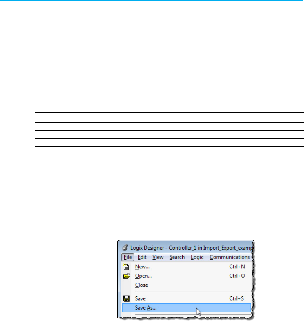
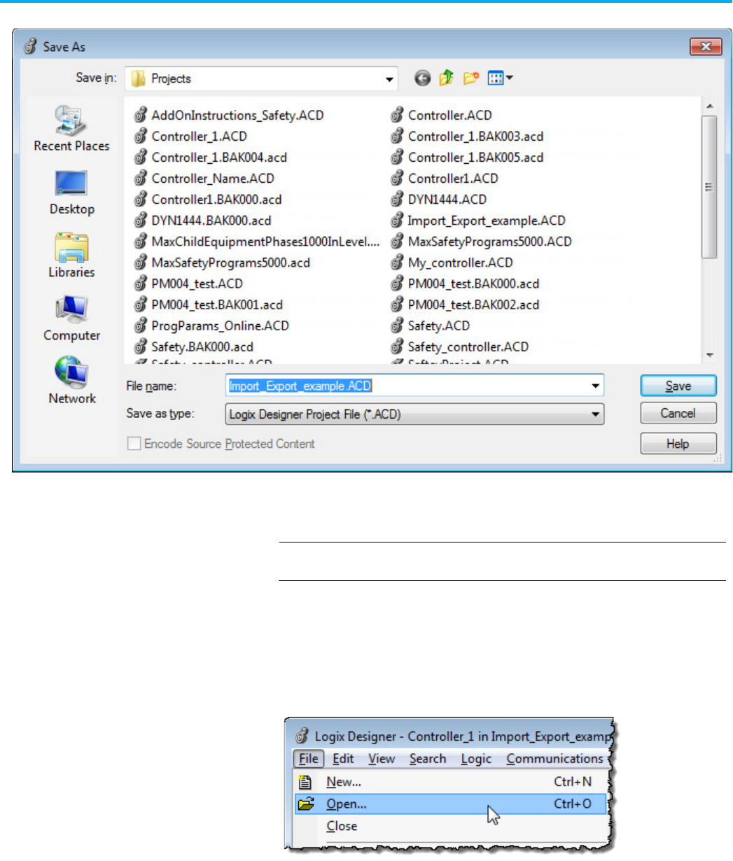
To export a project to an .L5K text file
1. Make sure the project you want to export is open.
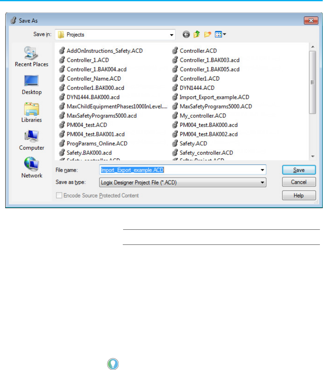
2. In the Logix Designer application, select File > Save As.
Import and export
introduction
Export a project to an .L5K
text file
Chapter 1 Import and export files
24 Publication 1756-RM014B-EN-P - November 2023
The Save As dialog box opens.
3. Browse to where you want to save the file.
4. In the File name field, type the name of the text file.
5. From the Save as type list, select the .L5K file format and select Save.
IMPORTANT
The application automatically saves any unsaved edits when you select OK.
Import controller information from a saved text file that has an .L5K
extension. This lets you use any text editor to create a project.
Do these steps to import an .L5K text file into a project.
1. In the Logix Designer application, from the File menu, choose Open.
Import an .L5K text file
Chapter 1 Import and export files
Publication 1756-RM014B-EN-P - November 2023 25
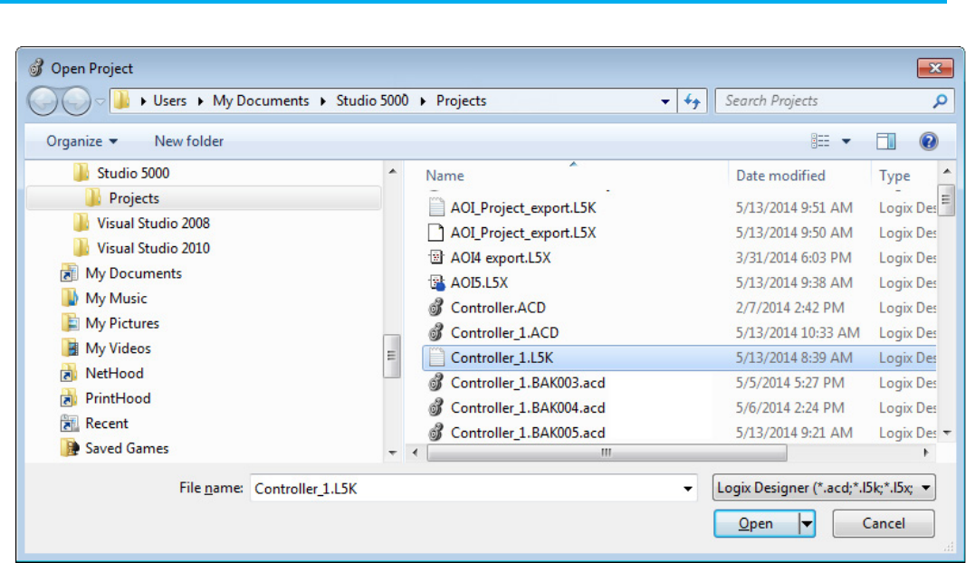
The Open Import Project dialog box opens.
2. Select the .L5K text file you want to import and select Open.
Chapter 1 Import and export files
26 Publication 1756-RM014B-EN-P - November 2023
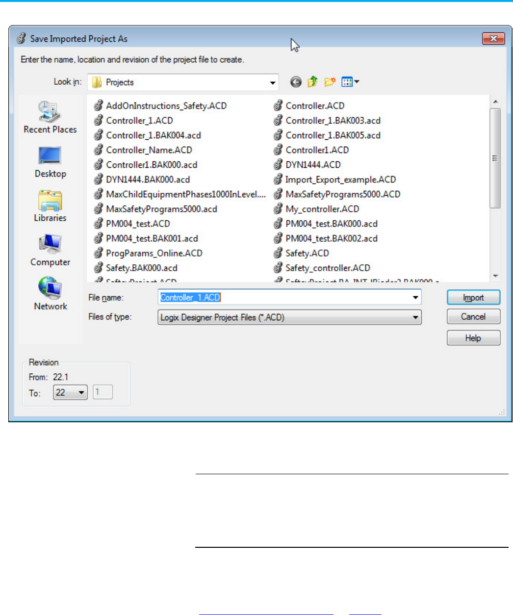
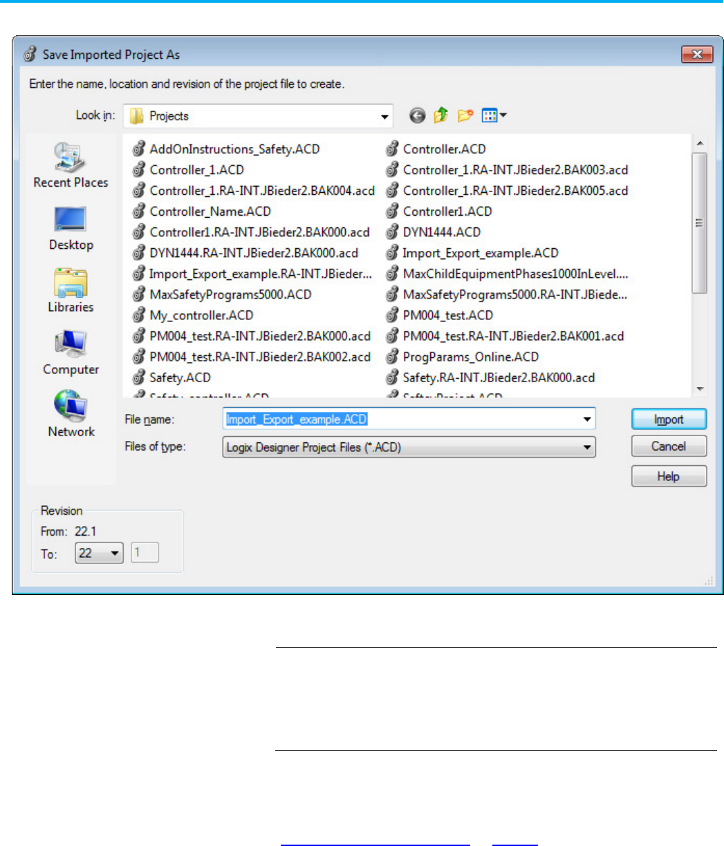
The Save Imported Project As dialog box opens.
3. Browse to where you want to save the imported project.
4. In the File name box, type the name for the imported project and select
Import.
IMPORTANT
If you import a project that has forces, the project defaults to
Forces Disabled
,
even if the project was exported with
Forces Enabled
.
When you import an .L5K file, the project changes so that you cannot go online
and access a previously downloaded controller. You must first upload from or
download to the controller. See
Maintaining Controller Access
..
See also
Maintaining Controller Access on page 39
Chapter 1 Import and export files
Publication 1756-RM014B-EN-P - November 2023 27
For projects with controllers that support OPC UA access, Logix Designer
exports the OpcUaAccess attribute for L5K elements that represent a tag.
These tags are included in the exported output:
• Tag elements (items in TAG collections in controller scope and
program scope)
• ConfigData (corresponds to Config Tag)
• InputData (corresponds to Input Tag)
• OutputData (corresponds to Output Tag)
The OpcUaAccess attribute is exported only when the OPC UA access of an
element representing a tag is different from the default value (None).
The OpcUaAccess attribute is exported also for alias tags.
Tip: During import, the OPC UA access of alias tags is ignored because alias tags have the same OPC
UA access as the tags to which they are pointing.
You can export a project to an XML file and use a text or XML editor to modify
the project. The exported file will be an .L5X format.
Do these steps to export from a project to an .L5X XML file.
1. Make sure the project you want to export from is already open.
2. In the Logix Designer application, select File > Save As.
Export a project to an .L5K
text file for projects with
OPC UA Access
Export a Project to an .L5X
XML File
Chapter 1 Import and export files
28 Publication 1756-RM014B-EN-P - November 2023
The Save As dialog box opens.
3. In the File name box, type the name of the file.
4. From the Save as type list, select.L5X file format and click Save.
Important:
The application automatically saves any unsaved edits when you select
OK
.
For projects with controllers that support OPC UA access, Logix Designer
exports the OpcUaAccess attribute for L5X elements that represent a tag.
These tags are included in the exported output regardless of the tags’ OPC UA
Access value:
• Tag (controller scope and program scope)
• ConfigTag
• InputTag
• OutputTag
The OpcUaAccess attribute is exported also for alias tags.
Tip: During import, the OPC UA access of alias tags is ignored because alias tags have the same OPC
UA access as tags to which they are pointing.
Import controller information from a saved XML file that has an .L5X
extension and is a full controller export. This lets you use any editor to create
a project.
Export a project to an .L5X
text file for projects with
OPC UA Access
Import an .L5X XML File
Chapter 1 Import and export files
Publication 1756-RM014B-EN-P - November 2023 29
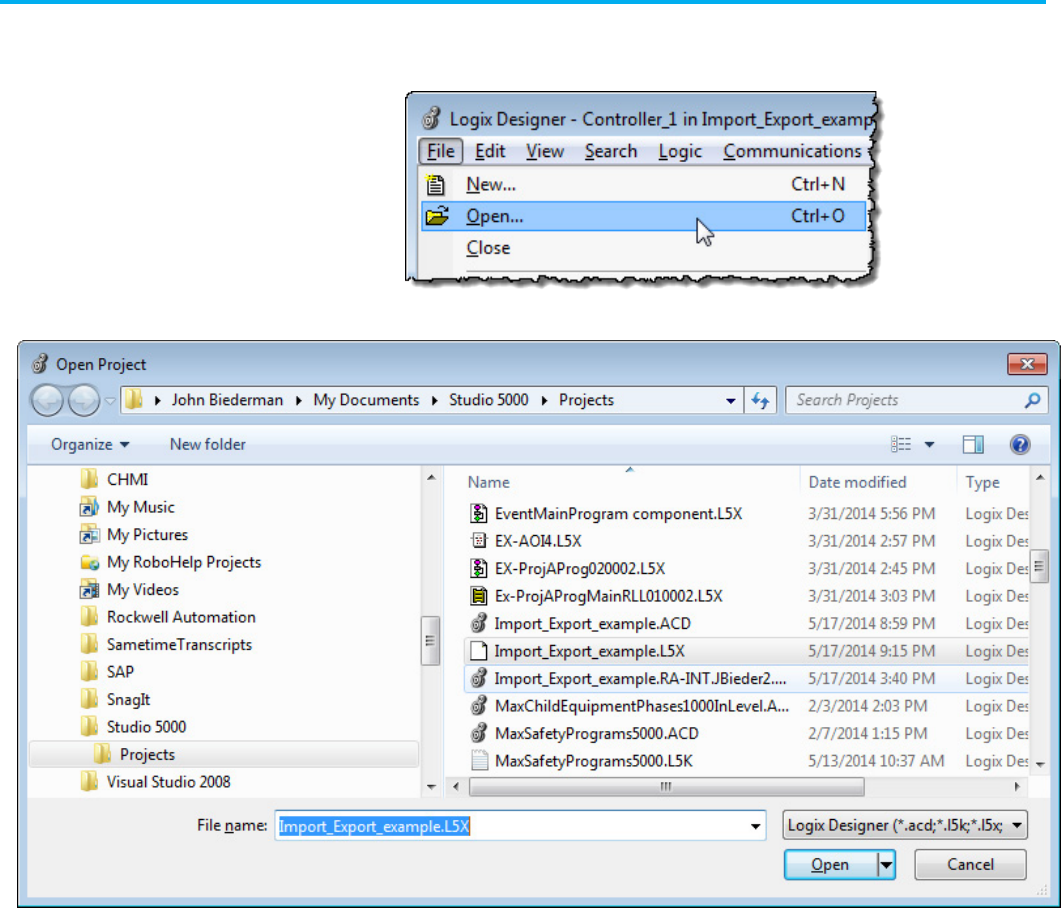
Do these steps to import a controller .L5X XML file into a project.
1. In the Logix Designer application, select File > Open.
The Open Project dialog box opens.
2. In the File name box, select the .L5X controller file you want to import
and select Open.
Chapter 1 Import and export files
30 Publication 1756-RM014B-EN-P - November 2023
The Save Imported Project As dialog box opens.
3. Browse to where you want to save the imported project.
4. In the File name box, type the name for the project and select Import.
IMPORTANT
If you import a project that has forces, the project defaults to
Forces Disabled
,
even if the project was exported with
Forces Enabled
.
When you import an .L5X file, the project changes so that you cannot go online
and access a previously downloaded controller. You must first upload from or
download to the controller. See
Maintaining Controller Access
.
See also
Maintaining Controller Access on page 39

Chapter 1 Import and export files
Publication 1756-RM014B-EN-P - November 2023 31
When you have a project open, you can export tags and logic comments to a
structured file that separates values with commas (.CSV file) or that separates
values with tabs (.TXT Unicode file). You can then use other applications, such
as Microsoft Excel or Notepad, to edit the tags and logic comments.
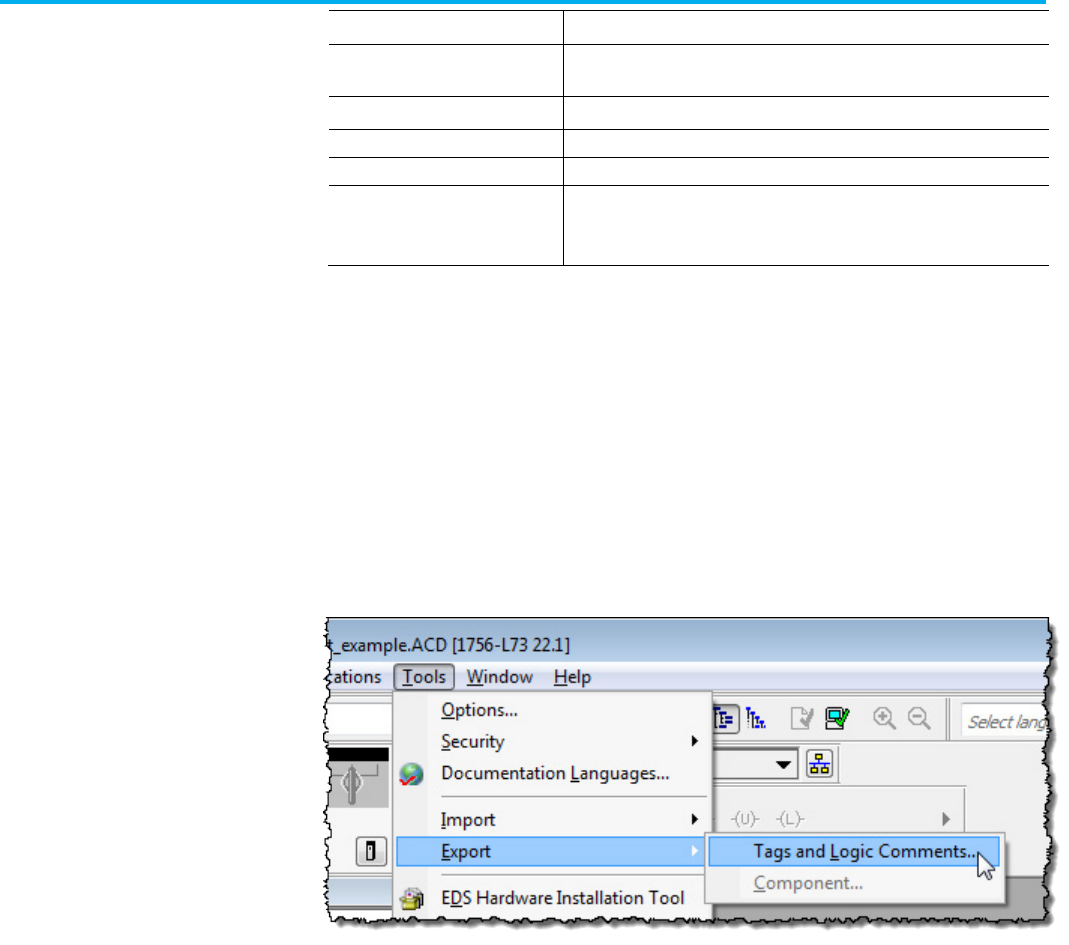
Do these steps to export tags and logic comments to a structured file.
1. Make sure the project from which you want to export tags and
comments is already open.
2. In the Logix Designer application, select Tools > Export > Tags and
Logic Comments.
Export to a .CSV or .TXT file
Chapter 1 Import and export files
32 Publication 1756-RM014B-EN-P - November 2023
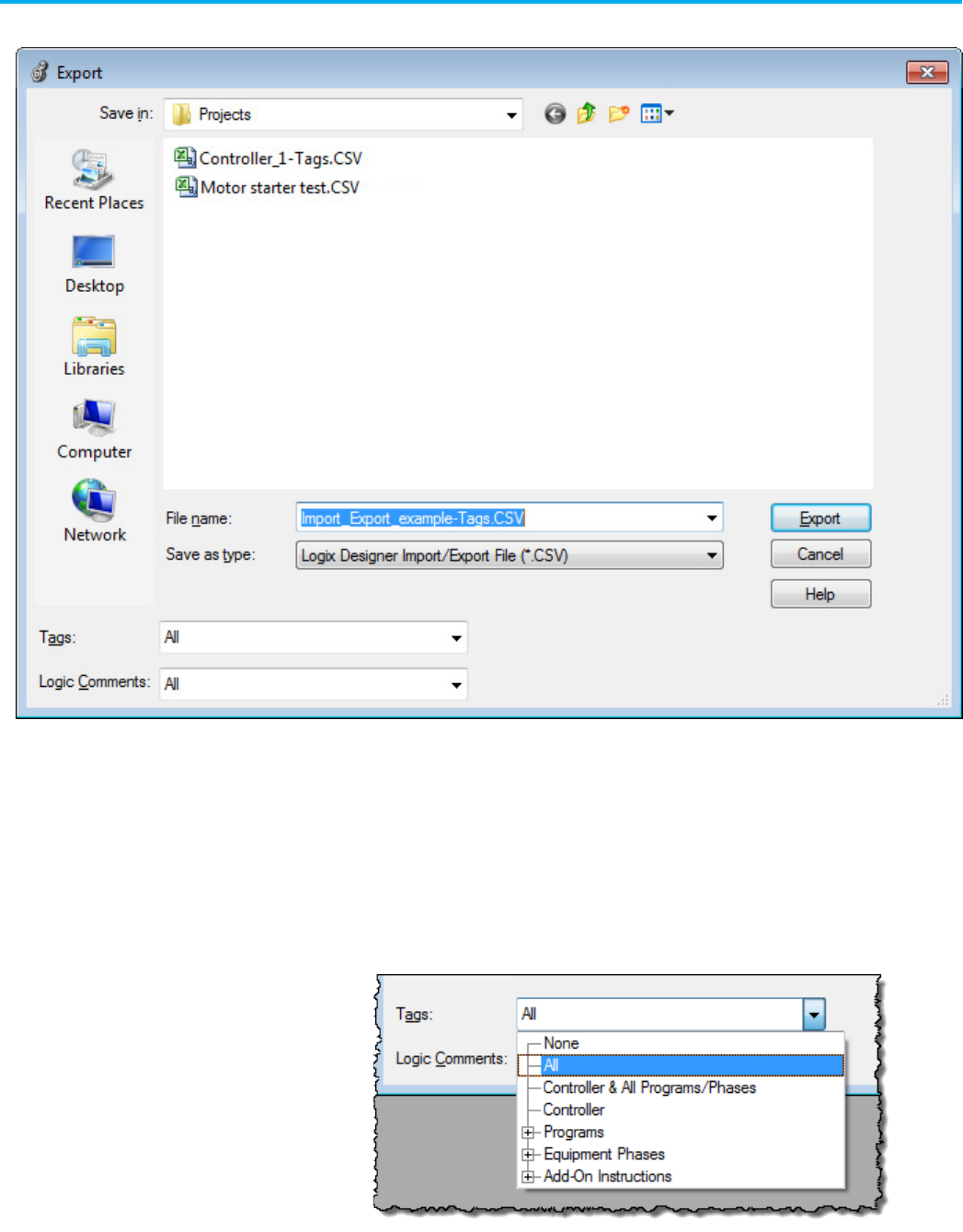
The Export dialog box opens.
3. In the File name box, type the name of the file to be exported.
4. From the Save as type list, select.CSV or .TXT format.
The .TXT import/export format supports double-byte characters, so
you can use this format for all languages, including Chinese, Japanese,
and Korean. The .CSV import/export format does not support
double-byte characters.
5. From the Tags and Logic Comments list, set the scope of the tags and
logic comments to be exported.
6. Select Export.
Chapter 1 Import and export files
Publication 1756-RM014B-EN-P - November 2023 33
Scope
Exported Material
All
All the tags (controller-scope, program-scope, equipment phase, and Add-On
Instruction) or logic comments in the project
Controller and All Programs/Phases
Tags only; all controller-scope, program-scope, and equipment phase tags
Controller
Tags only; the controller-scoped tags of the project
All Programs/Phases
Logic Comments only; all program and equipment phase comments
Programs
Equipment Phases
Add-On Instructions
The tags or logic comments of a specific program, equipment phase, or
Add-On Instruction
Import tags and logic comments from a saved .CSV file or .TXT file. This lets
you use other applications, such as Microsoft Excel or Notepad, to create and
edit tags
and logic comments.
To import .CSV or .TXT file
1. In the Logix Designer application, select Tools > Import > Tags and
Logic Comments.
Import a .CSV or .TXT file
Chapter 1 Import and export files
34 Publication 1756-RM014B-EN-P - November 2023
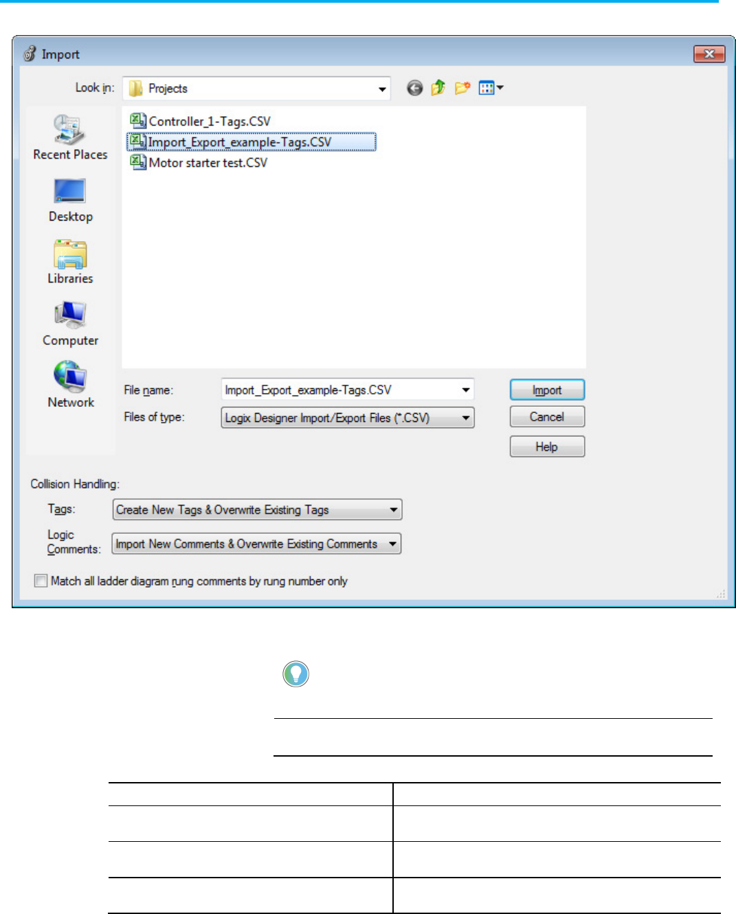
The Import dialog box opens.
2. In the File name box, select the .CSV or .TXT file to import.
3. From the File of type list, select .CSV or .TXT format.
Tip: Use the
File of type
list to filter .CSV or .TXT files in the
Import
dialog box.
4. From the Tags lists, specify how to handle tag collisions.
IMPORTANT
When you import tags, the tags in the import file might have the same name as
the tags that are already in the project. This condition is a collision.
If you want to:
From the Tags menu select:
Replace tags in the project with tags from the import file, in
addition to adding any new tags from the import file
Create New Tags & Overwrite Existing Tags
Keep tags that are in the project and discard colliding tags in the
import file, in addition to adding any new tags from the import file
Create New Tags & Overwrite Existing Tags
Replace tags in the project with tags from the import file, but do
not add any new tags from the import file
Create New Tags & Overwrite Existing Tags

Chapter 1 Import and export files
Publication 1756-RM014B-EN-P - November 2023 35
IMPORTANT
If you delete tags from the .CSV or .TXT file and import the file, the process does
not delete the tags from the controller project. Use the programming software
to delete tags from the controller project.
5. From the Logic Comments list, specify how to handle logic comment
collisions.
IMPORTANT
When you import logic comments, the possibility exists for the comments in the
import file to differ from the comments in the open project when both are
matched to the same logic.
If you want to:
From the Logic Comments list select:
Replace comments in the project with
comments from the import file, in addition to
adding any new comments from the import file
Import New Comments & Overwrite Existing Comments
Keep comments that are in the project and
discard colliding comments in the import file,
in addition to adding any new comments from
the import file
Import New Comments & Preserve Existing Comments
Replace comments in the project with
comments from the import file, but do not add
any new comments from the import file
Skip New Comments & Overwrite Existing Comments
6. Choose how to match comments to logic and select Import.
If you want rung comments
applied to:
Then:
The next rung that has the instruction, as
specified in the Owning Element, as its last
instruction on the rung
Make sure that the
Leave the Match all ladder diagram
rung comments by rung only
check box is cleared.
This is the default and recommended option.
The Location element is ignored.
The rung number specified in the Location
element
Select the
Match all ladder diagram rung comments by
rung only
check box.
This overrides the default and recommended option.
The Owning Element is ignored.
IMPORTANT
If a .CSV file or .TXT file contains changes to tags, including aliases, when you
import the file that the project changes such that you cannot go online and
access a previously downloaded controller. You must first upload from or
download to the controller.
If you only modify comments or descriptions before you import a .CSV file or
.TXT file, you can go online with the controller.
Starting with version 20, you can configure how source-protected content is
exported in .L5K and .L5X files.
By default, source-protected content is now exported in an encrypted format
to prevent viewing or modifying components in the system. A check box
option on the Workstation Options dialog box enables Add-On Instructions
and routines to be exported in a readable, cleartext format if the source keys
for those components are present in the sk.dat file. This lets you modify
protected content in a third-party tool, such as an XML editor.
Export source-protected
logic
Chapter 1 Import and export files
36 Publication 1756-RM014B-EN-P - November 2023
IMPORTANT
You must enable your workstation for source protection to use the cleartext option on
the
Workstation Option
dialog box. Otherwise, the check box is not available and
source-protected content is exported in an encrypted format.
Perform a partial or full-project export in cleartext when these parameters are
available:
• Your workstation has source protection enabled.
• The Workstation Option dialog box (Always Encode Source
Protection Content On Export) is not selected.
• The sk. dat file has been specified and it contains the source key
(password) for the content. For details, see the Logix5000 Controllers
Security Programming Manual , publication 1756-PM016.
If any of these requirements are absent, the content is exported in an
encrypted format.
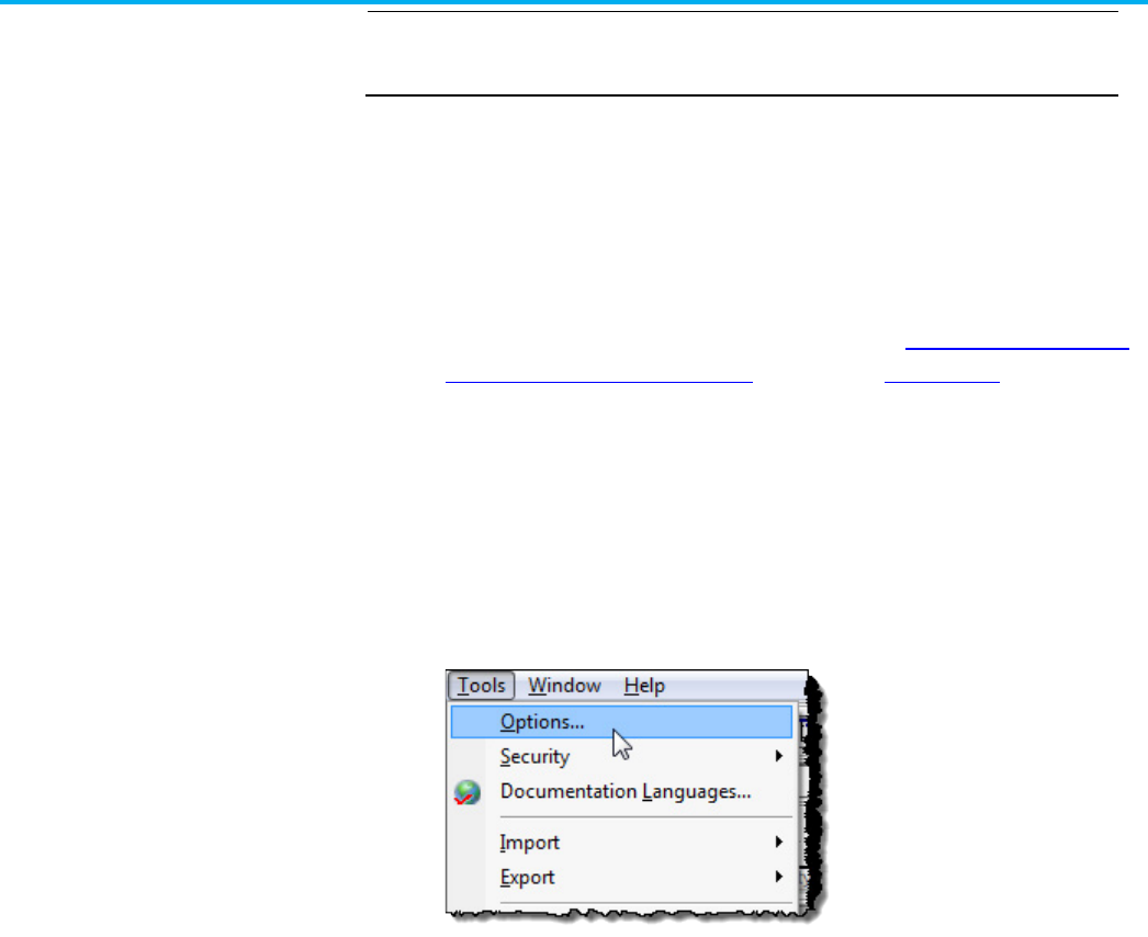
Use the same procedure for partial exporting a component or a full project in
readable text. Use these steps.
1. Open a project in the Logix Designer application that contains the
content that you want to export.
2. On the Menu bar, select Tools > Options.
Export in a Cleartext
Format
Chapter 1 Import and export files
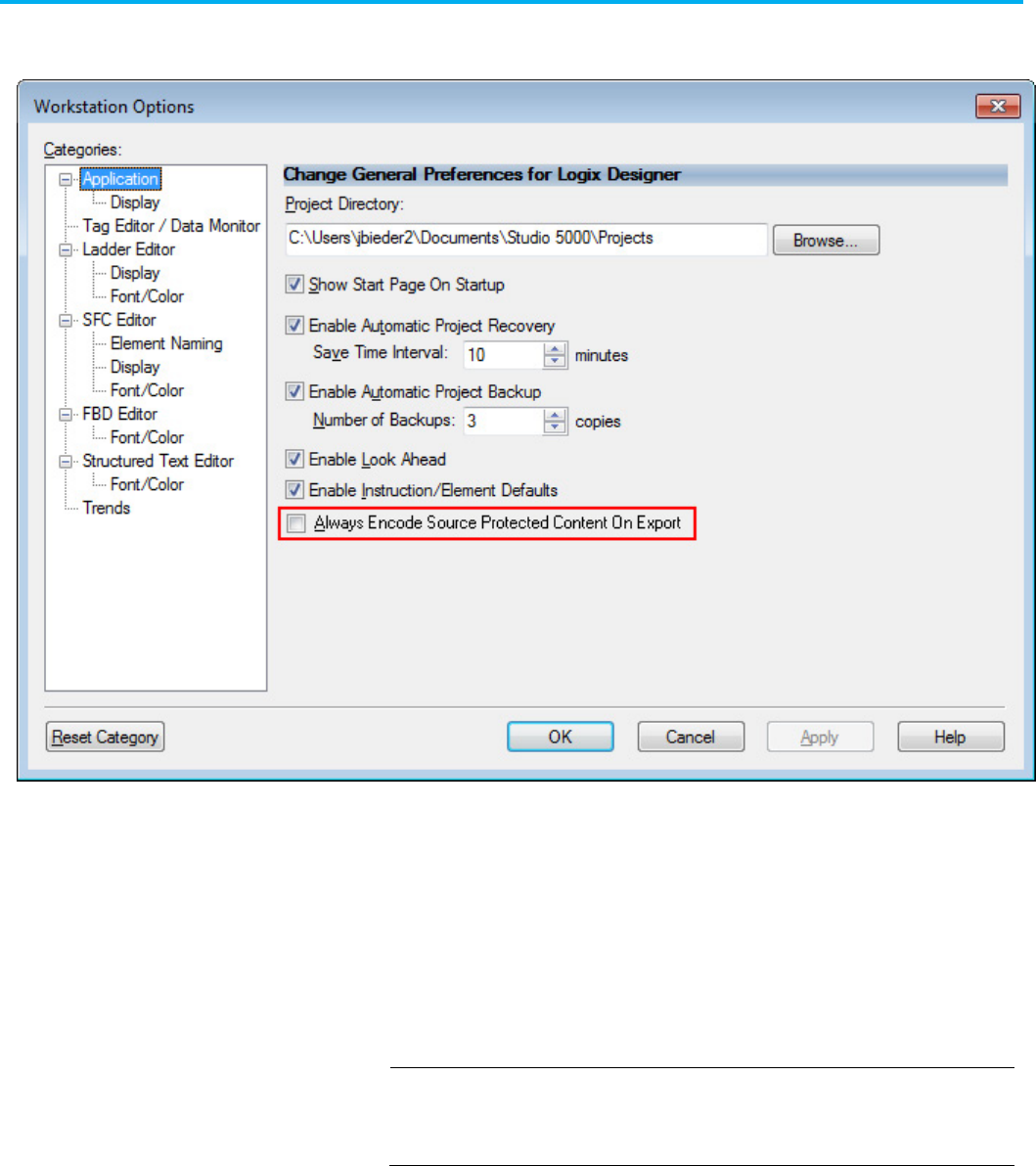
Publication 1756-RM014B-EN-P - November 2023 37
The Workstation Options dialog box opens with the export check box
option if your personal computer is enabled for source protection.
3. Clear the Always Encode Source Protected Content On Export check
box.
There is a similar check box on the Save As and Export component
dialog boxes that you must clear to export in cleartext from those
dialog boxes.
If you select the Always Encode Source Protected Content On Export
check box on the Workstation Options dialog box, the application
always exports source-protected content in an encrypted format, even
when source keys for the content are present.
IMPORTANT
You cannot copy source-protected content from version 21 of the application
and paste into earlier software versions. The pasting function is disabled in
previous software versions when source-protected content is placed on the
clipboard.
4. Select OK.
5. Take one of these actions:
• To export a component, right-click the component and choose
Export Routine. The component Export dialog box opens. Clear the
Encode Source Protected Content check box. Select the Export
button.
Chapter 1 Import and export files
38 Publication 1756-RM014B-EN-P - November 2023
• To save data for exporting as an .L5X or .L5K file, proceed to step 6.
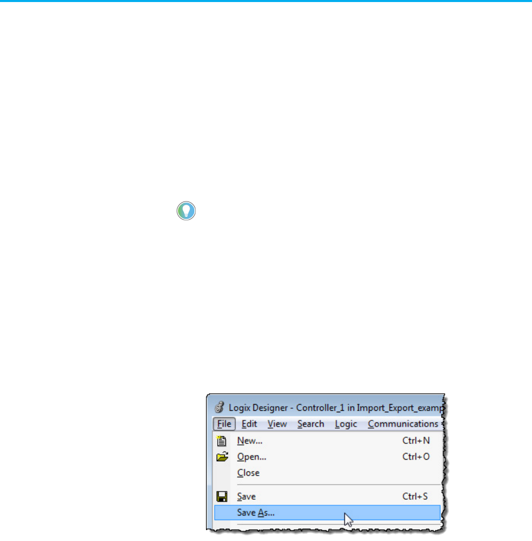
6. On the Menu bar, select File > Save As.
The Save As dialog box opens.
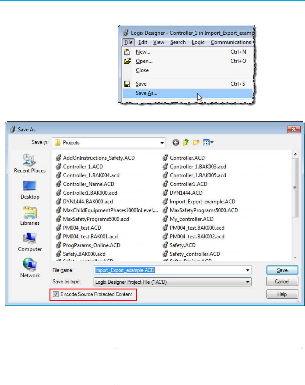
7. From the Save as type list, select the .L5K or .L5X option, depending on
your file type.
The Encode Source Protected Content check box is available when you
choose the .L5K or .L5X option.
IMPORTANT
The
Encode Source Protected Content
check box is only enabled when the
Always Encode Source Protected Content on Export
check box in the
Workstation Options
dialog box is cleared.
The
Encode Source Protected Content
check box also appears on the
component dialog box.
8. Clear Encode Source Protected Content check box to export content in
cleartext.
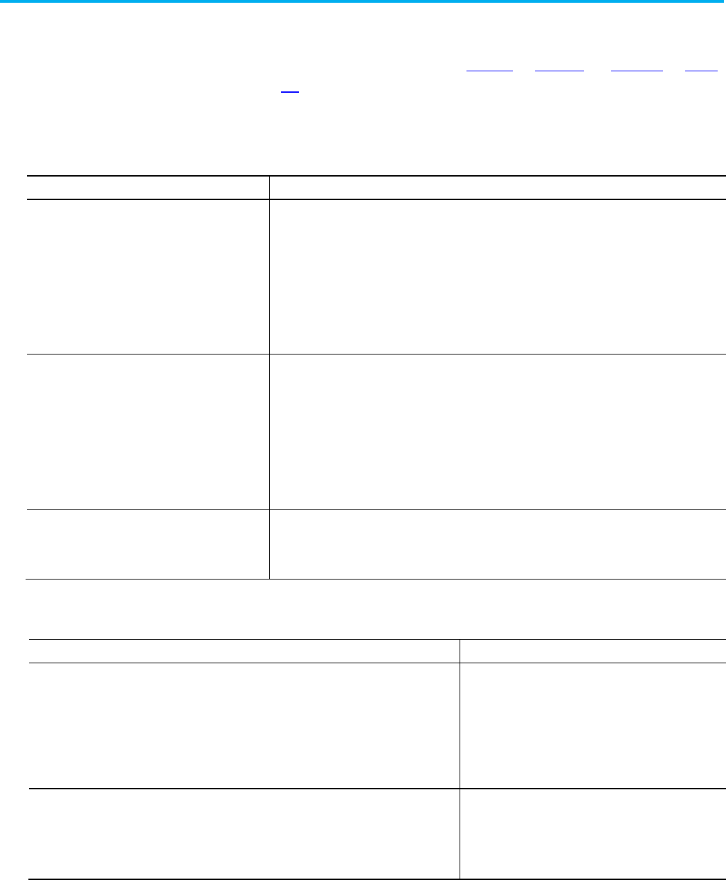
Chapter 1 Import and export files
Publication 1756-RM014B-EN-P - November 2023 39
9. Select Save.
See examples of encoded and unencoded codes for Add-On
Instructions and Routines on page 99 on page 95 and page 145 on page
157, respectively.
The controller manages project status to provide Logix Designer application
with the information to decide whether you can go online with a controller.
Information
Description
Creation Stamp The controller creates a creation stamp when you create, and import, a project and download the project to
the controller. The creation stamp in the controller and the project file must match to enable Logix Designer
application to go online with a controller.
If a project is exported to an .L5K file and then imported, the resulting project .ACD file gets a new creation
stamp. This means that the Logix Designer application views the imported project as different from the file
that was exported. The result is that you cannot use the new, imported project file to access a controller
that was downloaded with the original file, before it was exported. At this point, your only options are to
download again from the imported project file or to upload the controller contents to another project .ACD
file and merge with the documentation from one of the older project .ACD files.
Download Stamp The controller creates a download stamp on each download and stores this stamp in both the project and
the controller. When the creation stamp and the download stamp in the controller match those in the
project file, Logix Designer application can use the project to let you access the controller online.
If you change a project file when offline, that also clears the download stamp. This can occur when you
import from an .L5X file or if you import a .CSV file that creates a new tag or modifies a tag data type. When
you reset the download stamp, you can either download the project to the controller or upload the contents
from the controller. If you choose to upload, you lose any changes made through import. Note that
description and rung comment changes in a .CSV file do not reset the download stamp, so you can perform
some .CSV file imports and still maintain access to the controller.
Change Log Each time you change a controller online, the controller stores details about the change in a change log. If
there are more than 1000 changes made to the project file since you last went online with the controller,
you must either download the project to the controller or upload the contents from the controller. If you
choose to upload, you lose any changes made through import.
Given this status information, these situations prevent you from going online
with a controller.
Situations When You Cannot Go Online with a Controller
Possible Recovery
• More than 1000 controller edits were made.
• A download of another project copy with identical creation stamps occurred.
• Changes were made to the offline project, excluding documentation and tag value changes.
• A controller nonvolatile storage load occurred and the loaded image has the same creation stamp
but a different download stamp.
• A controller nonvolatile storage load occurred and the loaded image has the same creation and
download stamps but the change log is dated earlier than the project file.
• Full download to the controller
• Upload from the controller to a new project
• Upload from the controller and merge with an existing
project.
• The project was exported and then reimported. In this case, the software considers it a different
project and it has its own unique stamps.
• A different project, with different stamps, was downloaded.
• A controller nonvolatile storage load occurred, and the image was generated from a completely
different project file, with different stamps.
• Full download to the controller
• Upload from the controller to a new project.
An upload/merge of documentation is not possible in these
cases.
Maintaining controller
access
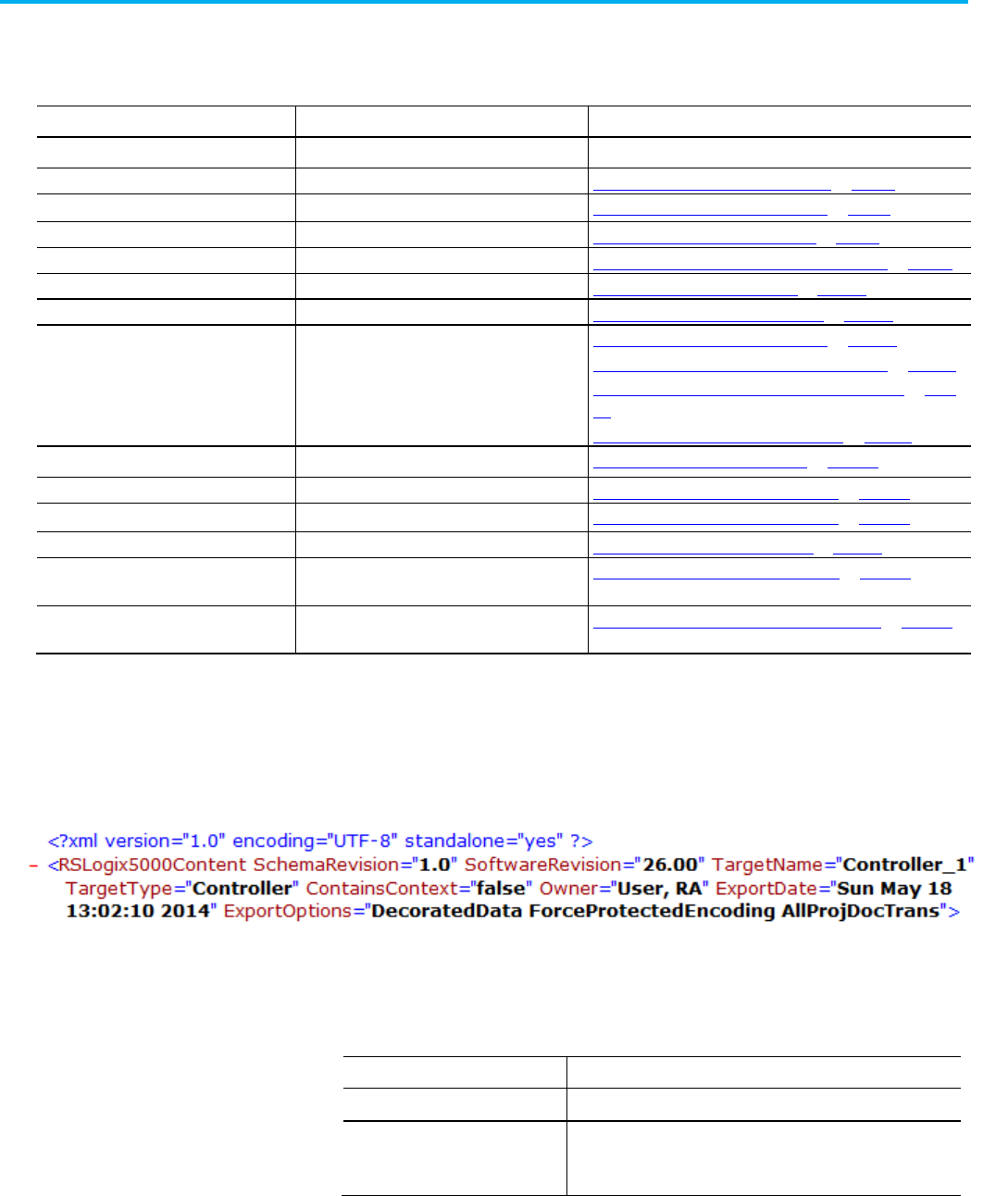
Chapter 1 Import and export files
40 Publication 1756-RM014B-EN-P - November 2023
The .L5X import/export file consists of the components listed in the table. The
.L5X format for each component is described in subsequent chapters of this
reference manual.
Component
Description
Chapter
<RSLogix5000Content> Describes version and export information This chapter, see example below
<Controller>
The controller
Chapter 2 Defining a Controller Component on page 53
<DataTypes> User-defined and I/O data structures Chapter 3 Defining a Datatype Component on page 67
<Modules>
Modules in the controller organizer
Chapter 4 Defining a Module Component on page 73
<AddOnInstructionDefinitions>
Add-On Instructions
Chapter 5 Defining an Add-On Instruction Component on page 85
<Tags>
Controller-scope tags
Chapter 6 Defining a Tag Component on page 105
<Programs>
Programs
Chapter 7 Defining a Program Component on page 153
<Routines> Ladder logic, function block diagram, sequential
function chart, and structured text routines
Chapter 8 Defining a Ladder Logic Routine on page 163
Chapter 9 Defining a Function Block Diagram Routine on page 175
Chapter 10 Defining a Sequential Function Chart Routine on page
199
Chapter 11 Defining a Structured Text Routine on page 221
<Tasks> Controller tasks Chapter 12 Defining a Task Component on page 243
<ParameterConnection>
Parameter connections
Chapter 13 Defining a Parameter Connection on page 247
<ParameterConnections> Program parameter connections Chapter 14 Defining a Parameter Connection on page 247
<Trends>
Any trend configured for the controller project
Chapter 15 Defining a Trend Component on page 251
<QuickWatchLists>
All quick watch lists configured in the controller
project
Chapter 16 Defining a Watch List Component on page 259
<CommPorts>, <CST>, and <WallClockTime> Controller configuration objects Chapter 17 Defining Controller Configuration Objects on page 263
The Controller component is the overall structure of the import/export file. It
contains the configuration information and logic of the controller project.
Preceding the Controller component is an optional XML declaration and a
required root element tag (RSLogix5000Content) that includes Logix
Designer application version information.
All components in an .L5X import/export file follow this structure.
<component_type [attribute_list]>
[body]
</component_type>
Item
Description
<component_type> The component begin tag.
attribute_list List of attributes for the component in the form:
attribute_name="attribute_value"
Separate attributes with a space.
.L5X file structure
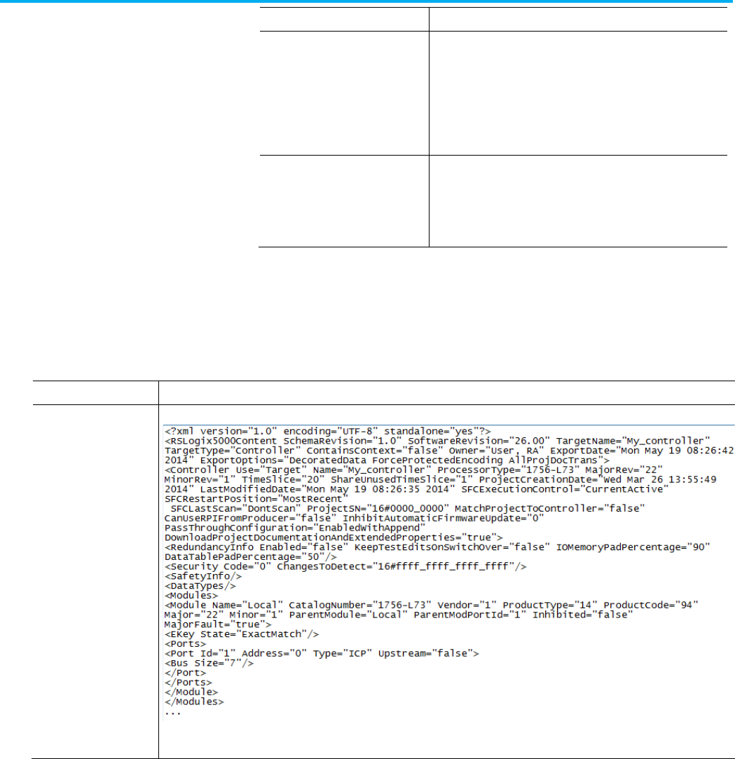
Chapter 1 Import and export files
Publication 1756-RM014B-EN-P - November 2023 41
Item
Description
body
The content of the component. The content could include any
subcomponents, for example, routines contained within a program,
or a description of the component. The content could also include
information about the component, for example, the data for a tag
component.
The body of the component is optional.
Internet
Explorer®</component_type>Internet
ExplorerInternet Explorer
The component end tag.
A component with no content in the body may combine its begin and
end tag as one tag:
(<component_type attribute_list />
The .L5X file is an ASCII file that is structured by using Extensible Markup
Language (XML). In addition to being able to open and modify the .L5X file in
a text editor, such as Notepad, you can also view the contents of the file in
Internet Explorer® and other tools that work with .XML files.
If you use:
You see:
A text editor, such as
Notepad
A text file, such as:
Edit this file in the text editor.
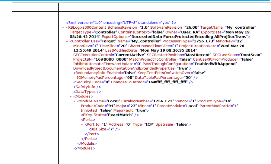
Chapter 1 Import and export files
42 Publication 1756-RM014B-EN-P - November 2023
If you use:
You see:
An Internet browser, such
as Internet Explorer
An .XML file, such as:
In the Internet browser, you can view only the file. Click the plus (+) and minus (-) to expand and collapse the viewable content. To edit
the file, open the file in a text editor.
The import/export feature L5X format is structured by using the Extensible
Markup Language (XML). The XML specification is an open standard and is
widely documented elsewhere. The only special convention used to describe
the L5X format in this document is that items shown in square brackets ([ ])
are optional.
White space characters include spaces, tabs, carriage returns, new line, and
form feeds. These characters can occur anywhere in an import/export file,
except in keywords or names. If white space characters occur outside of
descriptions, they are ignored.
Enter internal file comments to document your .L5X import files by using the
XML commenting format. The import process ignores these comments. Place
comments anywhere in an import/export .L5X file except within XML tag
elements. You cannot next a comment within another comment.
An XML comment begins with the character sequence <!-- and ends with the
character sequence -->. The comment appears between the begin and end
character sequence. The character sequence -- may not appear within a
comment. The text of the comment is ignored by the XML parser. This is an
example.
<!-- This is a comment that includes an XML start tag
element, <mytag>. The start tag is ignored by the parser.
-->
.L5X file conventions
L5X Internal file comments
Chapter 1 Import and export files
Publication 1756-RM014B-EN-P - November 2023 43
Descriptions of components are optional. Unlike internal file comments,
descriptions of components are imported. To add a description to a
component, add a <Description> start tag element as the first sub-element of
the component and then the description as a CDATA element in the body of
the <Description> element.
Component descriptions are brought into the project without being processed
by the XML parser for markup language. The description text is contained in a
CDATA element, a standard in the XML specification. A CDATA element
begins with the character sequence <![CDATA[ and ends with the character
sequence ]]>. None of the text within the CDATA element is interpreted by the
XML parser. The CDATA element preserves formatting so there is no need to
use control characters to enter formatted descriptions.
<Task Name="Task1" Type="PERIODIC" Rate="1000"
Priority="10" Watchdog="500"
DisableUpdateOutputs="false" InhibitTask="false">
<Description>
<![CDATA[
This is a task description with
a line feed and “ a quote.
]]>
</Description>
</Task>
Many boolean attributes in the L5K format may have a value of 1 (enabled) or
0 (disabled). In the L5X format, these same attributes have a value of true
(enabled) or false (disabled). Throughout this manual, a value of true or false
should be specified in the L5X format for any attributes that indicate a value
of 1 or 0.
Tags and data types support a radix attribute that specifies how to display the
associated numerical information in the Logix Designer application.
Radix Display Option
Example (based on 15 decimal)
Binary (uses a 2# prefix) 2#0000_0000_0000_1111
Octal (uses a 8# prefix)
8#000_017
Decimal
15
Hex (uses a 16# prefix)
16#000F
Ascii
‘$00$0F’
Exponential
1.5000000e+01
Float 15.0
The Logix Designer application imports the data in tags, modules, and data
structures (default values) with a <Data> element. You can import the <Data>
element in three different formats from the .L5X file: raw, L5K, and decorated
format. The format is indicated by a Format attribute.
<Tag Name="bINTtag" TagType="Base" DataType="INT" Radix="Decimal">
<Data>05 00</Data>
Component Descriptions
Boolean attribute values
Data display style
Data formats
Chapter 1 Import and export files
44 Publication 1756-RM014B-EN-P - November 2023
<Data Format="L5K">
<![CDATA[5 ]]>
</Data>
<Data Format="Decorated">
<DataValue DataType="INT" Radix="Decimal" Value="5"/>
</Data>
</Tag>
The application exports all data values in both raw and decorated data format
to the .L5X export file, with the exception that the InputTag under a module
connection does not have the raw data format exported.
If multiple formats are present in the .L5X file, they must appear in the order
of raw, L5K (if present), and decorated format. The data overwrites previous
values if different. For example, if the decorated data is manipulated in the
.L5X file, the decorated data values overwrite the raw data on import.
Raw data format
Raw data format is a hex dump of the data and includes hidden (config) data.
It is not intended to be readable. It is exported in the same format for all types
of data types. The raw data format is the default format. A format attribute is
not present if the <Data> element is in raw format.
Data Type
Raw Data Export Format
Atomic Example: an INT tag
<Data>05 00</Data>
Array of an Atomic Data
Type
Example: an array of 4 INT tags
<Data>02 00 03 00 04 00 05 00</Data>
Structure Data Type Example: a TIMER tag
<Data>00 00 00 00 01 00 00 00 05 00 00 00</Data>
Array of a Structure Data
Type
Example: an array of 3 TIMER tags
<Data>00 00 00 00 01 00 00 00 05 00 00 00 00 00 00 00 02 00 00 00
07 00 00 00 00 00 00 00 05 00 00 00 09 00 00 00</Data>
L5K Data Format
L5K data format is the same data format that appears in an .L5K file, wrapped
in a CDATA element. It is exported in the same format for all types of data
types. It is indicated by the Format="L5K" attribute in the <Data> start tag
element.
The L5K data format is not exported during a full project or component L5X
format. However, it is imported if present in an .L5X file. This format is
provided to enable customers to leverage the L5K data format as they convert
their auto generation tools from L5K to L5X format.
Data Type
L5K Data Export Format
Atomic Example: an INT tag
<Data Format="L5K">
<![CDATA[5 ]]>
</Data>

Chapter 1 Import and export files
Publication 1756-RM014B-EN-P - November 2023 45
Data Type
L5K Data Export Format
Array of an Atomic Data
Type
Example: an array of 4 INT tags
<Data Format="L5K">
<![CDATA[[2,3,4,5] ]]>
</Data>
Structure Data Type Example: a TIMER tag
<Data Format="L5K">
<![CDATA[[0,1,5] ]]>
</Data>
Array of a Structure Data
Type
Example: an array of 3 TIMER tags
<Data Format="L5K">
<![CDATA[[[0,1,5],[0,2,7],[0,5,9]] ]]>
</Data>
Decorated Data Format
Decorated data format is verbose and provides a human readable format of
the data. It was added to the L5X format in version 17 of the application, for
both L5X full project and L5X component exports and is recommended over
the L5K format. The format of the data varies by data type. The decorated data
format is indicated by the Format="Decorated" attribute in the <Data> start
tag element.
Data Type
Decorated Data Export Format
Atomic Example: an INT tag
<Data Format="Decorated">
<DataValue DataType="INT" Radix="Decimal" Value="5"/>
</Data>
Array of an Atomic Data
Type
Example: an array of 4 INT tags
<Data Format="Decorated">
<Array DataType="INT" Dimensions="4" Radix="Decimal">
<Element Index="[0]" Value="2"/>
<Element Index="[1]" Value="3"/>
<Element Index="[2]" Value="4"/>
<Element Index="[3]" Value="5"/>
</Array>
</Data>

Chapter 1 Import and export files
46 Publication 1756-RM014B-EN-P - November 2023
Data Type
Decorated Data Export Format
Structure Data Type
Example: a TIMER tag
<Data Format="Decorated">
<Structure DataType="TIMER">
<DataValueMember Name="PRE" DataType="DINT" Radix="Decimal"
Value="1"/>
<DataValueMember Name="ACC" DataType="DINT" Radix="Decimal"
Value="5"/>
<DataValueMember Name="EN" DataType="BOOL" Value="0"/>
<DataValueMember Name="TT" DataType="BOOL" Value="0"/>
<DataValueMember Name="DN" DataType="BOOL" Value="0"/>
</Structure>
</Data>
Array Structure Data Type Example: an array of 3 TIMER tags
<Data Format="Decorated">
<Array DataType="TIMER" Dimensions="3">
<Element Index="[0]">
<Structure DataType="TIMER">
<DataValueMember Name="PRE" DataType="DINT"
Radix="Decimal"
Value="1"/>
<DataValueMember Name="ACC" DataType="DINT"
Radix="Decimal"
Value="5"/>
<DataValueMember Name="EN" DataType="BOOL" Value="0"/>
<DataValueMember Name="TT" DataType="BOOL" Value="0"/>
<DataValueMember Name="DN" DataType="BOOL" Value="0"/>
</Structure>
</Element>
<Element Index="[1]">
<Structure DataType="TIMER">
<DataValueMember Name="PRE" DataType="DINT"
Radix="Decimal"
Value="2"/>
<DataValueMember Name="ACC" DataType="DINT"
Radix="Decimal"
Value="7"/>
<DataValueMember Name="EN" DataType="BOOL" Value="0"/>
<DataValueMember Name="TT" DataType="BOOL" Value="0"/>
<DataValueMember Name="DN" DataType="BOOL" Value="0"/>
</Structure>
</Element>
<Element Index="[2]">
<Structure DataType="TIMER">
<DataValueMember Name="PRE" DataType="DINT"
Radix="Decimal"
Chapter 1 Import and export files
Publication 1756-RM014B-EN-P - November 2023 47
Data Type
Decorated Data Export Format
Value="5"/>
<DataValueMember Name="ACC" DataType="DINT"
Radix="Decimal"
Value="9"/>
<DataValueMember Name="EN" DataType="BOOL" Value="0"/>
<DataValueMember Name="TT" DataType="BOOL" Value="0"/>
<DataValueMember Name="DN" DataType="BOOL" Value="0"/>
</Structure>
</Element>
</Array>
</Data>
Tip: If the decorated data for a tag exceeds 100 KB, the decorated data format will not be
exported. In this case, the raw data format will preserve the data values of the tag.
Force Values
Force values are indicated with an additional <ForceData> XML tag element
for both raw and L5K data formats. However, for decorated data, force values
are indicated with ForceValue attribute in the <DataValue> XML tag element
of the decorated data format.
<Tag Name="aDINTTag" TagType="Produced"
DataType="DINT" Radix="Decimal">
<ProduceInfo ProduceCount="1"
ProgrammaticallySendEventTrigger="false"
UnicastPermitted="false"/>
<Data>03 00 00 00</Data>

Chapter 1 Import and export files
48 Publication 1756-RM014B-EN-P - November 2023
<ForceData>00 00 00 00 FF FF FF FF 07 00 00
00
</ForceData>
<Data Format="L5K">
<![CDATA[3 ]]>
</Data>
<ForceData Format="L5K">
<![CDATA[[0,0,0,0,-1,-1,-1,-1,7,0,0,0] ]]>
</ForceData>
<Data Format="Decorated"><DataValue
DataType="DINT" Radix="Decimal" Value="3"
ForceValue="7"/>
</Data>
</Tag>
The .L5K import/export file contains these components. The L5K format for
each component is described in subsequent chapters of this reference
manual.
Component
Description
See Chapter
CONTROLLER The controller Chapter 2 Define a Controller Component on page 53
DATATYPE User-defined and I/O data structures Chapter 3 Define a Datatype Component on page 67
MODULE
Modules in the controller organizer
Chapter 4 Define a Module Component on page 73
ADD_ON_INSTRUCTION_
DEFINITION
Add-On Instructions Chapter 5 Define an Add-On Instruction Component on page 85
TAG Controller-scope tags Chapter 6 Define a Tag Component on page 105
PROGRAM
Program files
Chapter 7 Define a Program Component on page 153
ROUTINE
Ladder logic routines
Chapter 8 Define a Ladder Logic Routine on page 163
FBD_ROUTINE
Function block diagram routines
Chapter 9 Define a Function Block Diagram Routine on page 175
SFC_ROUTINE Sequential function chart routine Chapter 10 Define a Sequential Function Chart Routine on page 199
ST_ROUTINE
Structured text routine
Chapter 11 Define a Structured Text Routine on page 221
TASK Controller tasks Chapter 12 Define a Task Component on page 243
PARAMETER_CONNECTION Program Parameter connections Chapter 13 Define a Parameter Connection on page 247
TREND
Any trend configured for the controller project
Chapter 14 Define a Trend Component on page 251
WATCH_LIST All quick watch lists configured in the controller project Chapter 15 Define a Watch List Component on page 259
CONFIG Configuration information Chapter 16 Define Controller Configuration Objects on page 263
The CONTROLLER component is the overall structure of the import/export
file. It contains the configuration information and logic of the controller
project. The header remarks (optional) and the version statement come before
the CONTROLLER component.
Import-Export
Version := RSLogix 5000 16.00
Owner := User Name, Rockwell Automation
Exported := Tue May 13 08:39:40 2014
IE_VER := 2.20;
All components in an L5K import/export file follow this structure.
.L5K file structure
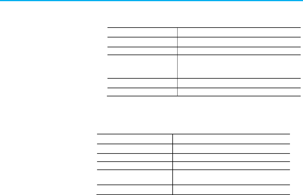
Chapter 1 Import and export files
Publication 1756-RM014B-EN-P - November 2023 49
Component_Type <component_name> [Attributes]
[body]
END_Component_Type
Item
Description
Component_Type The component.
component_name
A specific instance of the component.
Attributes Any attributes of the component.
Component descriptions appear as an attribute of the component.
Separate each attribute with a comma (,).
body Any subcomponents (children) of this component.
END_Component_Type
End of the component information.
The import/export feature L5K format described in this document is based on
the formats specified by the IEC 1131-3 specification.
Convention
Description
< > Items shown in angle brackets are required.
[ ]
Items shown in square brackets are optional.
user_value
Items in italics indicate user-supplied information.
LITERAL Items in all uppercase indicate a required keyword or symbol
that must be entered as shown.
"[" Items in double quotes are required characters.
White space characters include spaces, tabs, carriage returns, new line, and
form feeds. These characters can occur anywhere in an import/export file,
except in keywords or names. If white space characters occur outside of
descriptions, they are ignored.
Enter comments to document import files. The import process ignores these
comments. Place comments anywhere in an import/export file, except in
names and descriptions. Enter comments by starting the line (record) with
REMARK and a comma.
Descriptions of components are optional. Unlike internal file comments,
descriptions are imported. The description of a component is added as an
attribute of the component in the L5K format. Place the description within
double quotes. See this example.
TASK Task1 (Description := "Hello World",
Type := PERIODIC, Rate := 1000,
Priority := 10, Watchdog := 500,
DisableUpdateOutputs := No)
END_TASK
.L5K file conventions
L5K Internal file comments
Component descriptions
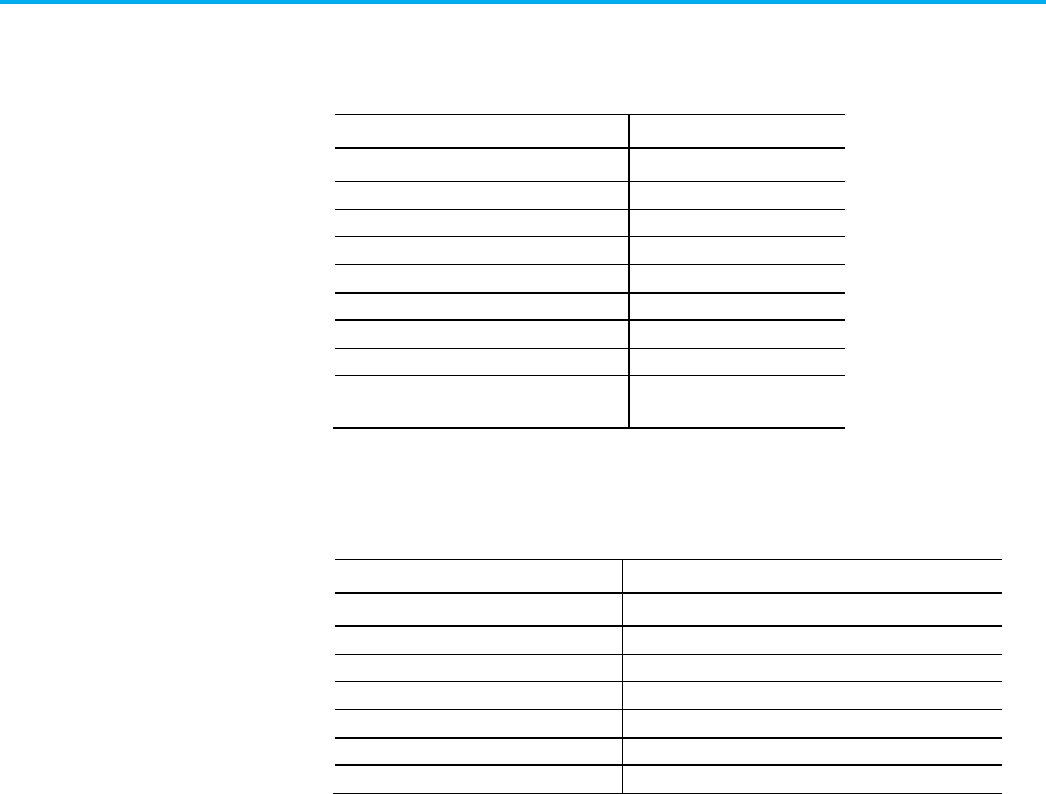
Chapter 1 Import and export files
50 Publication 1756-RM014B-EN-P - November 2023
To enter control characters in the description, precede the character with a
dollar sign ($). This table shows how to enter the supported control characters
in a description.
Character
Required Entry
$ $$
‘
$’
"
$Q
10 (line feed)
$L or $l
13,10 (carriage return, line feed)
$N or $n
12 (form feed) $P or $p
13 (carriage return) $R or $r
9 (tab)
$T or $t
xxxx (4-digit character code that represents a
hexadecimal value)
$xxxx
Tags and data types support a radix attribute that specifies how to display the
associated numerical information in the Logix Designer application.
Radix Display Option
Example (based on 15 decimal)
Binary (uses a 2# prefix) 2#0000_0000_0000_1111
Octal (uses a 8# prefix) 8#000_017
Decimal
15
Hex (uses a 16# prefix)
16#000F
Ascii ‘$00$0F’
Exponential
1.5000000e+01
Float
15.0
Starting with version 17 of the application, you can display project
documentation, such as tag descriptions and rung comments for any
supported localized language. You can store project documentation for
multiple languages in a single project file rather than in language-specific
project files. Define all the localized languages that the project will support
and set the current, default, and optional custom localized language. The
software uses the default language if the content of the current language is
blank for a particular component of the project. However, you can use a
custom language to tailor documentation to a specific type of project file user.
Enter the localized descriptions in your Logix Designer application project
when programming in that language or when using the import/export utility
to translate the documentation off-line and import it back into the project.
Once you enable project documentation in the Logix Designer application,
you can dynamically switch between languages as you use the software.
These project documentation variables are available for any supported
localized language:
Display style
Project documentation

Chapter 1 Import and export files
Publication 1756-RM014B-EN-P - November 2023 51
• Component descriptions in tags, routines, programs, equipment
phases, user-defined data types, and Add-On Instructions
• Engineering units and state identifiers added to tags, user-defined
data types, or Add-On Instructions
• Trends
• Controllers
• Alarm messages (in configuration of ALARM_ANALOG and
ALARM_DIGITAL tags)
• Tasks
• Property descriptions for a module in the Controller Organizer
• Rung comments, Sequential Function Chart text boxes, and Function
Block Diagram text boxes
The localized comments are exported in all formats, L5K, L5X, CSV, and TXT.
For more information on enabling a project to support multiple translations
of project documentation, see the online help.

Publication 1756-RM014B-EN-P - November 2023 53
Chapter 2
Define a controller component
This chapter explains the overall structure of the controller component.
The controller component contains the overall structure of a project to be
executed on one controller. It contains the configuration information and
logic that you download to one controller.
Refer to the L5X controller structure.
<Controller [controller_attributes]>
<Description>
<![CDATA[ text ]]>
</Description>
<RedundancyInfo [redundancyinfo_attributes]/>
<Security [security_attributes]/>
<PrimaryActionSets>
<PrimaryActionSet
PermissionSet=”PermissionSetName1”
IsPermissionSet=”true”>
<![CDATA[
encoded_cached_permissions ]]>
</PrimaryActionSet>
<PrimaryActionSet
PermissionSet=”PermissionSetName2”
IsPermissionSet=”false”>
<![CDATA[
encoded_cached_permissions ]]>
</PrimaryActionSet>
…
</ PrimaryActionSets >
</Security>
<SafetyInfo [safetyinfo_attributes]>
<SafetyTagMap>
[comma separated safety tag map]
</SafetyTagMap>
</SafetyInfo>
<DataTypes>
[datatype]
Controller component
introduction
Controller component
L5X controller structure

Chapter 2 Define a controller component
54 Publication 1756-RM014B-EN-P - November 2023
</DataTypes>
<Modules>
[module]
</Modules>
<AddOnInstructionDefinitions>
[addoninstructiondefinition]
</AddOnInstructionDefinitions>
<Tags>
[tag]
</Tags>
<Programs>
[program]
</Programs>
<Tasks>
[task]
</Tasks>
<ParameterConnections>
[parameter_connection]
</ParameterConnections>
<CommPorts>
[commport]
</CommPorts>
<CST [attribute_list] />
<WallClockTime [attribute_list] />
<Trends>
[trend]
</Trends>
<QuickWatchLists>s
[watch_list]
</QuickWatchLists>
< InternetProtocol [Internet_Protocol_Attributes] />
<EthernetPorts>
<EthernetPort [Ethernet_Port_Attributes] />
<EthernetPort [Ethernet_Port_Attributes] />
</EthernetPorts>
<EthernetNetwork [Ethernet_Network_Attributes] />
</Controller>
Tip: The L5X controller structure must be contained within an RSLogix5000Content root element
begin tag (<RSLogix5000Content>) and end tag (</RSLogix5000Content>). See the .L5X File Structure
on page 40 in Chapter 1 for more information.

Chapter 2 Define a controller component
Publication 1756-RM014B-EN-P - November 2023 55
Refer to this L5K CONTROLLER structure.
CONTROLLER <controller_name> [(Description := "text",
Controller_Attributes)]
[<DATATYPE declaration>]
[<MODULE declaration>]
[<ADD_ON_INSTRUCTION_DEFINITION declaration]
TAG
[<tag declarations>]
END_TAG
[<PROGRAM declaration>]
[<TASK declaration>]
[PARAMETER_CONNECTION declaration]
[<TREND declaration>]
[<QUICK_WATCH declaration>]
PRIMARY_ACTION_SET <permission_set_name>
(IsPermissionSet := Yes) :=
encoded_cached_permissions;
END_PRIMARY_ACTION_SET
[<CONFIG controller objects declaration>]
END_CONTROLLER
The table describes the elements comprising a controller.
L5X Item
L5K Item
Description
N/A
controller_name
The name of the controller project.
In L5X, use a name attribute on the <Controller> element.
Description Description User information about the controller project
RedundancyInfo
N/A
For L5X format, this element contains redundancy attributes.
Security
N/A
For L5X format, this element contains security attributes.
SafetyInfo
N/A
For L5X format, this element contains safety controller attributes.
DataTypes
DATATYPE
I/O and user-defined data structures
Modules
MODULE
Devices in the controller organizer
AddOnInstructionDefinitions ADD_ON_INSTRUCTION_
DEFINITION
Add-On instructions
Tags
TAG
Controller-scope tags
Programs
PROGRAM
Programs
Tasks
TASK
Tasks
ParameterConnections PARAMETER_CONNECTIONS Program parameter connections
Trends
TREND
Controller trends
QuickWatchLists QUICK_WATCH List of watch tags specified for a quick watch list
CommPorts, CST, WallClockTime
CONFIG
Characteristics of controller objects (status information)
PrimaryActionSet PRIMARY_ACTION_SET Cache of permissions for the Guest Users group that are associated with the
specified logical name or permission set.
L5K CONTROLLER structure
Controller elements

Chapter 2 Define a controller component
56 Publication 1756-RM014B-EN-P - November 2023
See the table for controller attributes and descriptions.
Attribute
Description
Use L5X only. Specify context or target.
Name L5X only. Specify the name of the controller component.
In L5K, the name is an element of the controller component.
ProcessorType
Specify the type of controller. (1756-L71, 1756-L71S, 1756-L72, 1756-L72S, 1756-L73, 1756-L73S,
1756-L74, 1756-L75, 1769-L16ER-BB1B, 1769-L18ER-BB1B, 1769-L18ERM-BB1B,
1769-L24ER-QB1B, 1769-L24ER-QBFC1B, 1769-L27ERM-QBFC1B, 1769-L30ER, 1769-L30ERM,
1769-L30ER-NSE, 1769-L33ER, 1769-L33ERM, 1769-L36ERM, Emulator)
Major L5K only. Specify the major revision number (1...127) of the controller.
MajorRev
L5X only. Specify the major revision number (1...127) of the controller.
MinorRev
L5X only. Specify the minor revision number (1...127) of the controller.
TimeSlice Percentage of available CPU time (10...90) that is assigned to communication.
ShareUnusedTimeSlice Specify whether to share an unused timeslice or not. Type a
0
to not share; type a
1
to
share.
PowerLossProgram Name of the program to be executed upon restart after a power loss.
MajorFaultProgram Name of the program to be executed when a major fault occurs.
CommPath Specify the devices in the communication path. The communication path ends with the
controller (\Backplane\1). This is exported only if you select manual configuration of the
communication path in RSLinx software.
CommDriver Specify the type of communication driver. This is the name of the selected driver in RSLinx
software. This is exported only if you select manual configuration of the communication
driver in RSLinx software.
RedundancyEnabled L5K only. Specify whether redundancy is used or not. Type a
0
to disable redundancy; type
a 1 to enable redundancy.
Enabled L5X only. Specify whether redundancy is used (true or false).
This attribute is on the <RedundancyInfo> tag element.
KeepTestEditsOnSwitchOver Specify whether to keep test edits on when a switchover occurs in a redundant system.
Type a
0
not to keep test edits on; type a
1
to keep test edits on.
For L5X, this attribute is on the <RedundancyInfo> tag element. Type
false
or
true
.
IOMemoryPadPercentage Specify the percentage (0...100) of I/O memory that is available to the system after the
download when configured for redundancy.
For L5X, this attribute is on the <RedundancyInfo> tag element.
DataTablePadPercentage
Specify the percentage (0...100) of the data table to reserve. If redundancy is not enabled,
type
0
. If redundancy is enabled, type
50
.
For L5X, this attribute is on the <RedundancyInfo> tag element.
SecurityCode L5K only. Specify whether the RSI Security Server is enabled for the controller. Type
0
if the
controller is unsecured; type a 10-digit, non-zero value if the controller is secured.
Code L5X only. Specify whether the RSI Security Server is enabled for the controller. Type
0
if the
controller is unsecured; type a 10-digit, non-zero value if the controller is secured.
This attribute is on the <Security> tag element.
Controller attributes

Chapter 2 Define a controller component
Publication 1756-RM014B-EN-P - November 2023 57
Attribute
Description
SFCExecutionControl Specify whether the SFC executes the current active steps before returning control
(CurrentActive) or whether the SFC executes all threads until reaching a false transition
(UntilFalse).
SFCRestartPosition Specify whether the SFC restarts at the most recently executed step (MostRecent) or at the
initial step (InitialStep).
SFCLastScan Specify how the SFC manages its state on a last scan. Select AutomaticReset,
ProgrammaticReset, or DontScan.
SerialNumber L5K only. Specify the serial number of the controller. If a serial number is specified, it is
imported into the project regardless of the MatchProjectToController setting. Type a 32-bit,
hexadecimal number with the 16# prefix, such as 16#0012_E2BC.
ProjectSN L5X only. Specify the serial number of the controller. If a serial number is specified, it is
imported into the project regardless of the MatchProjectToController setting. Type a 32-bit,
hexadecimal number with the 16# prefix, such as 16#0012_E2BC.
MatchProjectToController Specify whether to be sure that the project matches the controller or not. Type
Yes
or
No
.
InhibitAutomaticFirmwareUpdate Specify whether to inhibit the automatic update of controller firmware. Type a
0
to not
inhibit; type a 1 to inhibit.
CurrentProjectLanguage
Specify the current project language for a project documentation project.
DefaultProjectLanguage
Specify the default project language for a project document at on project.
ControllerLanguage
Specify the controller project language for a project document at on project.
CanUseRPIFromController Specify whether the consumed tags in the controller can connect to the producer with an
RPI provided by the producer (true or false).
SecurityAuthorityID ID of the FactoryTalk Diagnostics
®
to which your controller is bound.
For L5X only, this attribute is on the <Security> tag element.
SecurityAuthorityURI Network path to the FactoryTalk Diagnostics to which your controller is bound.
For L5X only, this attribute is on the <Security> tag element.
PermissionSet Name of the set of permissions, configured in FactoryTalk Security, to apply to this object.
For L5X only, this attribute is on the <Security> tag element.
IsPermissionSet Indicates if this is associated with a permission set or a logical name.
ChangesToDetect Mask that specifies the controller events that you wish to track.
For L5X only, this attribute is on the <Security> tag element.
TrustedSlots
Mask defining the slots through which the trusted communication is permitted to the
controller.
For L5X only, this attribute is on the <Security> tag element
PassThroughConfiguration For L5K and L5X. Indicates the pass through state of documentation for the project.
Type
Disabled
,
Enabled
, or
EnabledWithAppend
DownloadProjectDocumentationAndExtendedProperties For L5K and L5X. Indicates the download project documentation configuration setting of
the project.
DownloadCustomProperties For L5K and L5X. Indicates the download custom properties configuration setting of the
project. Only applies if the project is already configured to
DownloadProjectDocumentation.
Rockwell recommends setting this attribute to false only during startup testing to improve
download speeds during commissioning testing. It should be set to true for the normal
operating state of a system. For L5X, the setting is
true
or
false
. For L5K, the setting is
1 (true) or 0 (false).
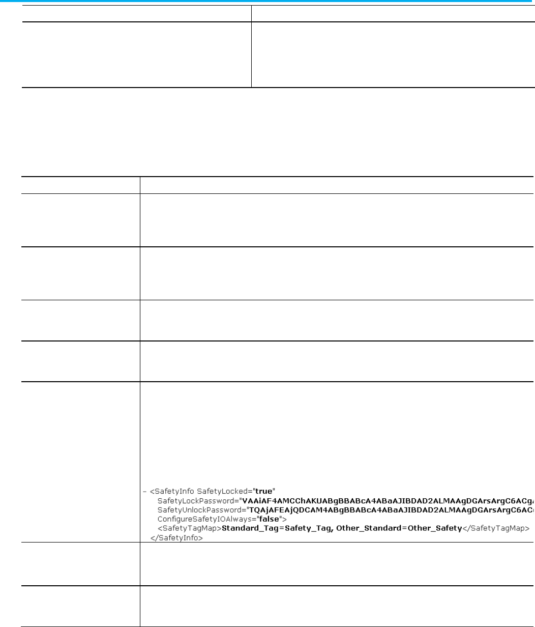
Chapter 2 Define a controller component
58 Publication 1756-RM014B-EN-P - November 2023
Attribute
Description
EtherNetIPMode The EtherNet/IP Mode describes the relationship between the CIP EtherNet/IP ports and
the physical Ethernet ports. The CIP EtherNet/IP port can be configured as one of two
modes:
• Dual-IP
•
Linear/DLR
For safety controllers, specify these attributes for the Controller component,
in addition to those previously described.
Attribute
Description
SafetySignature
Specifies the safety signature control as defined in the controller properties. This value is exported only; it is ignored on
import.
For L5X, this attribute is on the <SafetyInfo> tag element.
SafetyLocked Displays whether the safety controller is locked or not. This value is exported only; it is ignored on import. This value will be Yes
or No.
For L5X, this attribute is on the <SafetyInfo> tag element. Type true or false.
SafetyLockPassword Specifies the lock password in the controller. This value is encrypted on export.
For L5X, this attribute is on the <SafetyInfo> tag element.
SafetyUnlockPassword Specifies the unlock password in the controller. This value is encrypted on export.
For L5X, this attribute is on the <SafetyInfo> tag element.
SafetyTagMap L5K only as an attribute. Specify the tags in the safety tag map. Place double quotes around the tags. Each entry must end with
a comma and carriage return. This is an example.
"StdTag1=SafeTag1,
StdTag2=SafTag2"
For L5X, a <SafetyTagMap> element is a subelement under the <SafeyInfo> element. Specify the tags in the safety tag map in
the body of the <SafetyTagMap> element Do not use quotes. Separate mappings with a comma and a space.
ConfigureSafetyIOAlways Specify whether to configure safety I/O when replacing safety I/O. Type
Yes
or
No
.
For L5X, this attribute is on the <SafetyInfo> tag element. Type
true
or
false
.
SignatureRunModeProtect Indicates whether you can modify the safety signature when in Run mode.
For L5X only, this attribute is on the <SafetyInfo> tag element.
Observe these guidelines when defining a controller:
Controller attributes in a
safety controller system
Controller guidelines
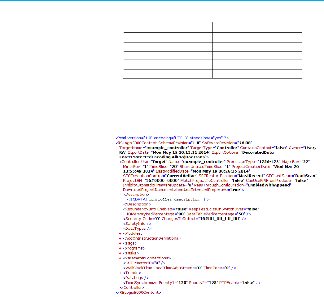
Chapter 2 Define a controller component
Publication 1756-RM014B-EN-P - November 2023 59
• All declarations must be ordered in the prescribed syntax.
• The maximum number of tasks vary by the controller type.
Controller
Maximum Number of Tasks
ControlLogix® 32
SoftLogix™ 5800
32
FlexLogix™
8
CompactLogix™ 4
DriveLogix™
4
• There can be only one continuous task.
• Programs can be scheduled under only one task.
• There can be a maximum of 1000 programs under a task.
• Scheduled programs must be defined.
L5X Controller Example
L5X Safety Controller Example
Controller component
examples
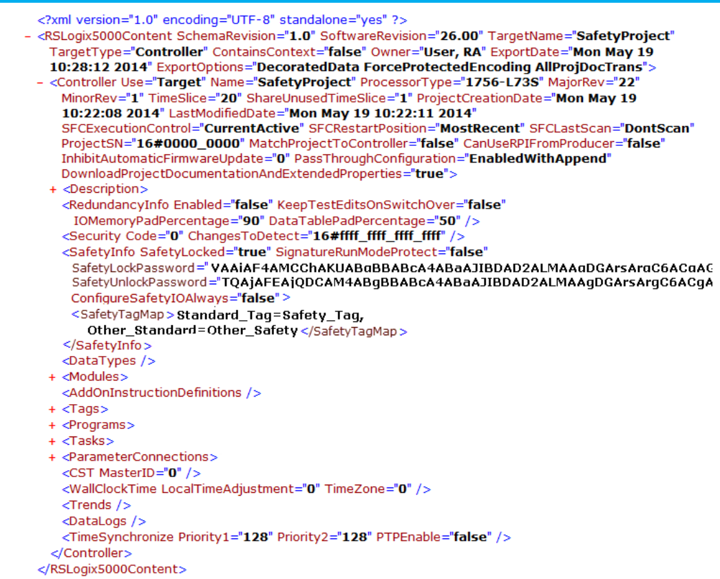
Chapter 2 Define a controller component
60 Publication 1756-RM014B-EN-P - November 2023
L5K CONTROLLER Example
CONTROLLER example_controller (Description := "controller
description",
ProcessorType := "1756-L73",
Major := 22,
TimeSlice := 20,
ShareUnusedTimeSlice := 1,
RedundancyEnabled := 0,
KeepTestEditsOnSwitchOver := 0,
DataTablePadPercentage := 50,
SecurityCode := 0,
ChangesToDetect := 16#ffff_ffff_ffff_ffff,
SFCExecutionControl := "CurrentActive",
SFCRestartPosition := "MostRecent",
SFCLastScan := "DontScan",
SerialNumber := 16#0000_0000,

Chapter 2 Define a controller component
Publication 1756-RM014B-EN-P - November 2023 61
MatchProjectToController := No,
CanUseRPIFromProducer := No,
InhibitAutomaticFirmwareUpdate := 0,
PassThroughConfiguration := EnabledWithAppend,
DownloadProjectDocumentationAndExtendedProperties :=
Yes)
MODULE Local (Parent := "Local",
ParentModPortId := 1,
CatalogNumber := "1756-L73",
Vendor := 1,
ProductType := 14,
ProductCode := 94,
Major := 22,
Minor := 1,
PortLabel := "RxBACKPLANE",
ChassisSize := 7,
Slot := 0,
Mode := 2#0000_0000_0000_0001,
CompatibleModule := 0,
KeyMask := 2#0000_0000_0001_1111)
END_MODULE
TAG
END_TAG
PROGRAM MainProgram (MAIN := "MainRoutine",
MODE := 0, DisableFlag := 0)
TAG
END_TAG
ROUTINE MainRoutine
END_ROUTINE
END_PROGRAM
TASK MainTask (Type := CONTINUOUS,
Rate := 10, Priority := 10, Watchdog := 500,
DisableUpdateOutputs := No, InhibitTask := No)
MainProgram;
END_TASK
PARAMETER_CONNECTION
END_PARAMETER_CONNECTION
CONFIG ASCII(XONXOFFEnable := 0,
DeleteMode := 0, EchoMode := 0,
TerminationChars := 65293, AppendChars := 2573,
BufferSize := 82)

Chapter 2 Define a controller component
62 Publication 1756-RM014B-EN-P - November 2023
END_CONFIG
CONFIG ControllerDevice END_CONFIG
CONFIG CST(SystemTimeMasterID := 0) END_CONFIG
CONFIG DF1(DuplicateDetection := 1,
ErrorDetection := BCC Error, EmbeddedResponseEnable
:= 0,
DF1Mode := Pt to Pt, ACKTimeout := 50,
NAKReceiveLimit := 3, ENQTransmitLimit := 3,
TransmitRetries := 3, StationAddress := 0,
ReplyMessageWait := 5, PollingMode := 1,
MasterMessageTransmit := 0, NormalPollNodeFile :=
"<NA>",
NormalPollGroupSize := 0, PriorityPollNodeFile :=
"<NA>",
ActiveStationFile := "<NA>", SlavePollTimeout :=
3000,
EOTSuppression := 0, MaxStationAddress := 31,
TokenHoldFactor := 1, EnableStoreFwd := 0,
StoreFwdFile := "<NA>")
END_CONFIG
CONFIG FileManager END_CONFIG
CONFIG SerialPort(BaudRate := 19200,
Parity := No Parity, DataBits := 8 Bits of Data,
StopBits := 1 Stop Bit, ComDriverId := DF1,
PendingComDriverId := DF1, RTSOffDelay := 0,
RTSSendDelay := 0, ControlLine := No Handshake,
PendingControlLine := No Handshake,
RemoteModeChangeFlag := 0,
PendingRemoteModeChangeFlag := 0,
ModeChangeAttentionChar := 27,
PendingModeChangeAttentionChar := 27,
SystemModeCharacter := 83,
PendingSystemModeCharacter := 83,
UserModeCharacter := 85,
PendingUserModeCharacter := 85,
DCDWaitDelay := 0)
END_CONFIG
CONFIG WallClockTime(LocalTimeAdjustment := 0, TimeZone
:= 0)
CONFIG InternetProtocol [(Internet_Protocol_Attributes)]

Chapter 2 Define a controller component
Publication 1756-RM014B-EN-P - November 2023 63
END_ CONFIG
CONFIG EthernetPort1 [(Internet_Protocol_Attributes)]
END_ CONFIG
CONFIG EthernetPort2 [(Internet_Protocol_Attributes)]
CONFIG EthernetNetwork [(Ethernet_Network_Attributes)]
END_CONFIG
END_CONTROLLER
L5K Safety CONTROLLER Example
CONTROLLER example_safety_controller (Description :=
"Safety Project",
ProcessorType := "1756-L73S",
Major := 22,
TimeSlice := 20,
ShareUnusedTimeSlice := 1,
RedundancyEnabled := 0,
KeepTestEditsOnSwitchOver := 0,
DataTablePadPercentage := 50,
SecurityCode := 0,
ChangesToDetect := 16#ffff_ffff_ffff_ffff,
SFCExecutionControl := "CurrentActive",
SFCRestartPosition := "MostRecent",
SFCLastScan := "DontScan",
SerialNumber := 16#0000_0000,
MatchProjectToController := No,
CanUseRPIFromProducer := No,
SafetyLocked := No,
SignatureRunModeProtect := No,
ConfigureSafetyIOAlways := No,
InhibitAutomaticFirmwareUpdate := 0,
PassThroughConfiguration := EnabledWithAppend,
DownloadProjectDocumentationAndExtendedProperties :=
Yes)
MODULE Local (Parent := "Local",
ParentModPortId := 1,
CatalogNumber := "1756-L73S",
Vendor := 1,
ProductType := 14,
ProductCode := 148,
Major := 22,
Minor := 1,
PortLabel := "RxBACKPLANE",
ChassisSize := 7,
Slot := 0,

Chapter 2 Define a controller component
64 Publication 1756-RM014B-EN-P - November 2023
Mode := 2#0000_0000_0000_0001,
CompatibleModule := 0,
KeyMask := 2#0000_0000_0001_1111,
SafetyNetwork :=
16#0000_3c77_0315_5105)
END_MODULE
MODULE example_safety_controller:Partner
(Parent := "Local", ParentModPortId := 1,
CatalogNumber := "1756-L7SP", Vendor := 1,
ProductType := 14, ProductCode := 146,
Major := 22, Minor := 1,
PortLabel := "RxBACKPLANE", Slot := 1,
Mode := 2#0000_0000_0000_0000,
CompatibleModule := 0,
KeyMask := 2#0000_0000_0001_1111,
SafetyNetwork := 16#0000_0000_0000_0000)
END_MODULE
TAG
END_TAG
PROGRAM MainProgram (Class := Standard,
MAIN := "MainRoutine", MODE := 0,
DisableFlag := 0)
TAG
END_TAG
ROUTINE MainRoutine
END_ROUTINE
END_PROGRAM
PROGRAM SafetyProgram (Class := Safety,
MAIN := "MainRoutine", MODE := 0,
DisableFlag := 0)
TAG
END_TAG
ROUTINE MainRoutine
END_ROUTINE
END_PROGRAM
TASK MainTask (Type := CONTINUOUS,

Chapter 2 Define a controller component
Publication 1756-RM014B-EN-P - November 2023 65
Class := Standard, Rate := 10,
Priority := 10, Watchdog := 500,
DisableUpdateOutputs := No, InhibitTask := No)
MainProgram;
END_TASK
TASK SafetyTask (Type := PERIODIC,
Class := Safety, Rate := 20,
Priority := 10, Watchdog := 20,
DisableUpdateOutputs := No, InhibitTask := No)
SafetyProgram;
END_TASK
PARAMETER_CONNECTION
END_PARAMETER_CONNECTION
CONFIG ASCII(XONXOFFEnable := 0,
DeleteMode := 0, EchoMode := 0,
TerminationChars := 65293,
AppendChars := 2573, BufferSize := 82)
END_CONFIG
CONFIG ControllerDevice END_CONFIG
CONFIG CST(SystemTimeMasterID := 0) END_CONFIG
CONFIG DF1(DuplicateDetection := 1,
ErrorDetection := BCC Error,
EmbeddedResponseEnable := 0,
DF1Mode := Pt to Pt, ACKTimeout := 50,
NAKReceiveLimit := 3, ENQTransmitLimit := 3,
TransmitRetries := 3, StationAddress := 0,
ReplyMessageWait := 5, PollingMode := 1,
MasterMessageTransmit := 0,
NormalPollNodeFile := "<NA>",
NormalPollGroupSize := 0,
PriorityPollNodeFile := "<NA>",
ActiveStationFile := "<NA>",
SlavePollTimeout := 3000, EOTSuppression := 0,
MaxStationAddress := 31, TokenHoldFactor := 1,
EnableStoreFwd := 0, StoreFwdFile := "<NA>")
END_CONFIG
CONFIG FileManager END_CONFIG

Chapter 2 Define a controller component
66 Publication 1756-RM014B-EN-P - November 2023
CONFIG SerialPort(BaudRate := 19200,
Parity := No Parity, DataBits := 8 Bits of Data,
StopBits := 1 Stop Bit, ComDriverId := DF1,
PendingComDriverId := DF1, RTSOffDelay := 0,
RTSSendDelay := 0, ControlLine := No Handshake,
PendingControlLine := No Handshake,
RemoteModeChangeFlag := 0,
PendingRemoteModeChangeFlag := 0,
ModeChangeAttentionChar := 27,
PendingModeChangeAttentionChar := 27,
SystemModeCharacter := 83,
PendingSystemModeCharacter := 83,
UserModeCharacter := 85,
PendingUserModeCharacter := 85, DCDWaitDelay :=
0) END_CONFIG
CONFIG WallClockTime(LocalTimeAdjustment := 0,
TimeZone := 0)
CONFIG InternetProtocol [(Internet_Protocol_Attributes)]
END_ CONFIG
CONFIG EthernetPort1 [(Internet_Protocol_Attributes)]
END_ CONFIG
CONFIG EthernetPort2 [(Internet_Protocol_Attributes)]
CONFIG EthernetNetwork [(Ethernet_Network_Attributes)]
END_CONFIG
END_CONTROLLER

Publication 1756-RM014B-EN-P - November 2023 67
Chapter 3
Define a Datatype component
This chapter explains the overall structure of the datatype component.
Datatype components define the data types used in the logic you export.
Refer to the L5X datatype structure.
<DataTypes>
<DataType [DataType_Attributes]>
<Description>
<![CDATA[ text ]]>
</Description>
<EngineeringUnit>
<![CDATA[ engineering_unit_text ]]>
</EngineeringUnit>
<Members>
[member_list]
</Members>
</Datatype
</DataTypes>
Refer to this L5K datatype structure.
DATATYPE <DataType_name> ([Description := "text",
EngineeringUnit := "text",
DataType_Attributes])
[member_definitions]
END_DATATYPE
See the table for .L5X and .L5K datatype element items and descriptions.
L5X Item
L5K Item
Description
N/A
DataType_name
The name of the data type.
In L5X, use a Name attribute on the <DataType> element.
Description Description User information about the data type.
Datatype component
introduction
Datatype component
L5X datatype structure
L5K datatype structure
Datatype elements
Chapter 3 Define a Datatype component
68 Publication 1756-RM014B-EN-P - November 2023
L5X Item
L5K Item
Description
EngineeringUnit
EngineeringUnit
(optional) User-specified description of the unit of the value, such as feet, gallons,
and kilos.
Members
member_definitions
Defines the members of the data structure.
See the table for datatype attributes and descriptions.
Attribute
Description
Name
L5X only. Specify the name of the data type.
In L5K, the name is an element of the data type statement.
Family (L5X)
FamilyType (L5K)
Specify StringFamily for a string data type.
Specify NoFamily for all other data types.
Class L5X only. Type
User
.
There are two kinds of datatype members:
• Bit member—a member in which only a single bit of information is
accessed.
• Nonbit member—a member that is defined as another data type, such
as SINT, INT, DINT, and COUNTER.
Refer to the L5X datatype member structure.
<Members>
<Member [Member_Attributes]>
<Description>
<![CDATA[ text ]]>
</Description>
<EngineeringUnit>
<![CDATA[ engineeringunit_unit_text ]]>
</EngineeringUnit>
<State0>
<![CDATA[ state0_text ]]>
</State0>
<State1>
<![CDATA[ state1_text ]]>
</State1>
</Member>
</Members>
Datatype attributes
Datatype member
L5X datatype member
structure
Chapter 3 Define a Datatype component
Publication 1756-RM014B-EN-P - November 2023 69
Refer to this L5K datatype member structure.
<TypeName> <MemberName> ([Description := "text",
EngineeringUnit := "text",
State0 := "text",
State1 := "text",
Member_Attributes]);
A bit member uses this syntax:
BIT <BitName> <HostMemberName> : <BitPosition> [(Attributes)];
This table contains .L5X and .L5K datatype member elements and their
descriptions.
L5X Item
L5K Item
Description
N/A
TypeName
The name of the data type of the member.
In L5X, use a DataType attribute on the <Member> element.
N/A
MemberName
The name of the member.
In L5X, use a Name attribute on the <Member> element.
Description Description User information about the member.
EngineeringUnit EngineeringUnit (optional) User-specified description of the unit of the value, such as feet, gallons,
and kilos.
State0 State0 (optional) For Boolean member only. User-specified description of what the Zero
state of the Boolean value is.
State1 State1 (optional) For Boolean member only. User-specified description of what the One
state of the Boolean value is.
N/A
BitName
The name of the bit member.
In L5X, use a Name attribute on the <Member> element.
N/A
HostMemberName
The hidden host member of bit members.
In L5X, use a Target attribute on the <Member> element.
N/A
BitPosition
The bit position in the hidden host member.
In L5X, use a BitNumber attribute on the <Member> element.
See the table for datatype member attributes and descriptions.
Attribute
Description
Name L5X only. Specify the name of the member.
In L5K, the member name is an element of the member statement.
Dimension L5X only. Specify the dimensions of the member. Type
0
if atomic or a non-zero value for an array.
Radix
Specify decimal, hex, octal, binary, exponential, float, ASCII, or date/time.
Hidden
Specify if the member is a hidden member of the structure. Type 1 or 0 (or true or false for L5X)
Target
The name of the hidden host member.
BitNumber
The bit position in the host member.
Max (optional) User-specified maximum value for the member. Only valid for members with non-Boolean atomic
datatypes.
L5K datatype member
structure
Datatype member elements
Datatype member
attributes
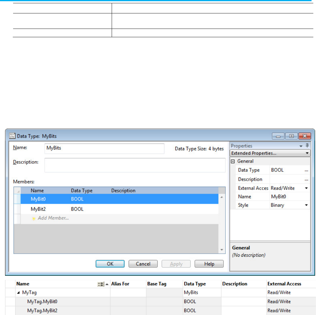
Chapter 3 Define a Datatype component
70 Publication 1756-RM014B-EN-P - November 2023
Attribute
Description
Min
(optional) User-specified minimum value for the member. Only valid for members with non-Boolean atomic
datatypes.
External Access Specify the external access outside of the controller to the member. Specify
Read/Write
,
Read Only
, or
None
.
All data types are allocated in 8-bit boundaries. A single bit of storage is not
allowed, so a member cannot be a BOOL data type. To access a single bit, use
the BIT declaration. BIT allows access to a single bit within a host member
(a non-bit member).
For example, create a user-defined datatype called MyBits and a tag called
MyTag of type MyBits:
zzzzzzzzzzMyBits0 is the host member of MyBit0 and MyBit1.
The host member is normally a hidden member because only the bit
references are visible when you define a tag of the datatype. Logix Designer
appends the z characters to the host member name to prevent a bit overlay
error. If you remove the z characters, the datatype can still be imported but it
cannot be modified.
Bit members cannot be defined before their host members. Note that
BitPosition zero is the least significant bit.
This is the datatype syntax for this example in the L5K format.
Bit members
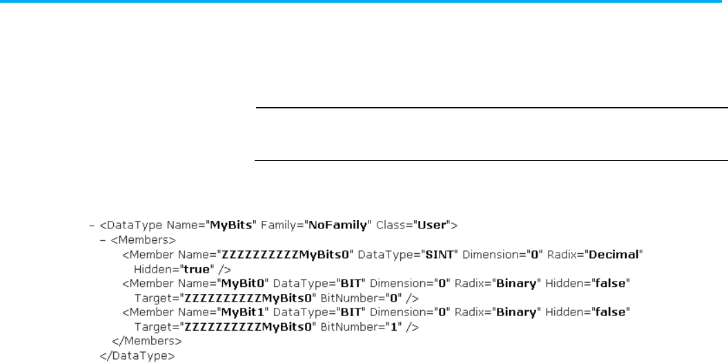
Chapter 3 Define a Datatype component
Publication 1756-RM014B-EN-P - November 2023 71
DATATYPE MyBits (FamilyType := NoFamily)
SINT ZZZZZZZZZZMyBits0 (Hidden := 1);
BIT MyBit0 ZZZZZZZZZZMyBits0 : 0 (Radix := Binary);
BIT MyBit1 ZZZZZZZZZZMyBits0 : 1 (Radix := Binary);
END_DATATYPE
IMPORTANT
There must be a space between the host member name, colon, and the bit position
because type names can contain a colon (for example, I/O structures). The space
indicates where the type name ends.
This is the datatype syntax for this example in the L5X format.
Observe these guidelines when defining a datatype:
• Datatypes must be defined first within the controller body.
• Datatypes can be defined out of order. For example, if Type1 depends
on Type2, Type2 can be defined first.
• Datatypes can be unverified. For example if Type1 depends on Type2
and Type2 is never defined, then Type1 will be accessible as an
unverified type. Type2 will be typeless type. Tags of Type1 may be
created but not of Type2.
• Datatype members can be arrays but only one dimension is allowed.
• These datatypes cannot be used in a user-defined datatype:
• ALARM_ANALOG
• ALARM_DIGITAL
• AXIS types
• COORDINATE_SYSTEM
• MOTION_GROUP
• MESSAGE
• MODULE
• If one user-defined datatype references a second user-defined data
type defined in the file, the second user-defined datatype appears
before the first one in the import/export file.
L5X DataType example
Datatype guidelines
Datatype component
examples
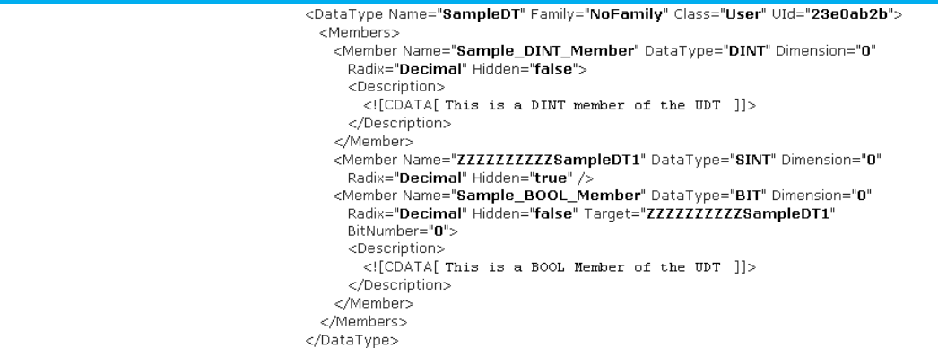
Chapter 3 Define a Datatype component
72 Publication 1756-RM014B-EN-P - November 2023
L5K DATATYPE example
DATATYPE MyStructure (FamilyType := NoFamily)
DINT x;
TIMER y[3] (Radix := Decimal);
SINT MyFlags (Hidden :=1);
BIT aBit0 MyFlags : 0 (Radix := Binary);
BIT aBit1 MyFlags : 1 (Radix := Binary);
END_DATATYPE

Publication 1756-RM014B-EN-P - November 2023 73
Chapter 4
Define a module component
This chapter explains the overall structure of the module component.
A module component defines any modules used by logic you export. For
example, the module component can contain I/O modules referenced by I/O
tags, modules accessed by GSV/SSV instructions, or controllers referenced in
consumed tags.
Refer to the L5X module structure.
<Modules>
<Module [Module_Attributes]>
<Description>
<![CDATA[ text ]]>
</Description>
<EKey [Ekey_Attributes]/>
<Ports>
<Port [Port_Attributes]
<Bus [Bus_Attributes]/>
</Port>
</Ports>
<Communications [Communications_Attributes]>
<ConfigTag [ConfigTag_Attributes]>
[data]
</ConfigTag>
<ConfigScript [ConfigScript_Attributes]>
[data]
</ConfigScript>
[connections]
</Communications>
<ExtendedProperties
[ExtendedProperties_Attributes]>
[extendedpropertiesdata]
</ExtendedProperties>
Module component
introduction
Module component
L5X module structure
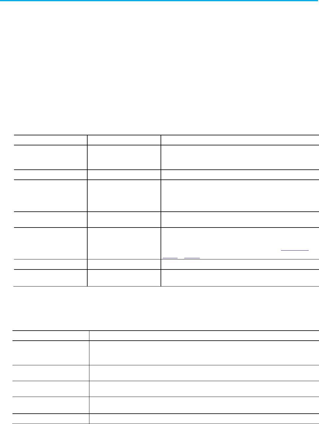
Chapter 4 Define a module component
74 Publication 1756-RM014B-EN-P - November 2023
</Module>
</Modules>
Refer to this L5K MODULE structure.
MODULE <device_name> [(Description := "text",
Module_Attributes)]
[ConfigData := <initial_value>;]
[ConfigScript:=<initial_value>;]
[ExtendedProp := <text>]
[connection_list]
END_MODULE
See these .L5X and .L5K module elements and their descriptions.
L5X Item
L5K Item
Description
N/A
device_name
The name of the module.
In L5X, use a Name attribute on the <Module> element.
Description Description User information about the module.
EKey N/A Keying information for the module.
In L5K, this information is in the CompatibleModule and KeyMask attributes on the
MODULE.
Ports N/A Port information for the module, which is the physical connector for the module that
attaches the module to the bus. Each module has at least one port.
ConfigTag or ConfigData ConfigData Operating characteristics of the module.
In L5X, the data for the tag is defined with <Data> elements. See Chapter 1 Data
Formats on page 43 for more information.
ExtendedProperties ExtendedProp Additional profile data stored in the controller in an XML format.
connections
connection_list
(zero or more CONNECTION entries)
Connection characteristics for the module.
Refer to these module attributes and their descriptions.
Attribute
Description
Name L5X only. Specify the name of the module.
In L5K the name is an element of the statement.
Parent L5K only. If this module is a child to another module, specify the name of the parent module. The parent module must be
defined before any child module.
ParentModule L5X only. If this module is a child to another module, specify the name of the parent module. The parent module must be
defined before any child module.
ParentModPortID (L5K)
ParentModPortID (L5X)
If this module is a child to another module, specify the number of the port on the parent module that connects to this child
module. The parent module must be defined before any child module.
CatalogNumber
Specify the catalog number of the module.
L5K MODULE structure
Module elements
Module attributes

Chapter 4 Define a module component
Publication 1756-RM014B-EN-P - November 2023 75
Attribute
Description
Vendor
Specify the vendor of the module. A number 1 indicates Allen-Bradley®.
For L5X, this attribute is on the <EKey> element if the State attribute has a value of
Custom
.
ProductType Specify the product type of the module.
For L5X, this attribute is on the <EKey> element if the State attribute has a value of
Custom
.
ProductCode Specify the product code of the module.
For L5X, this attribute is on the <EKey> element if the State attribute has a value of
Custom
.
Major Specify the major revision number (1...127) of the module.
For L5X, this attribute is on the <EKey> element if the State attribute has a value of
Custom
.
Minor Specify the minor revision number (1...255) of the module.
For L5X this attribute is on the <EKey> element if the State attribute has a value of
Custom
.
UserDefinedVendor Specify the vendor of a non-Allen-Bradley module. Type a number to indicate the vendor.
UserDefinedProductType
Specify the product type of a non-Allen-Bradley module.
UserDefinedProductCode
Specify the product code of a non-Allen-Bradley module.
UserDefinedMajor
Specify the major revision number (1...127) of a non-Allen-Bradley module.
UserDefinedMinor Specify the minor revision number (1...255) of a non-Allen-Bradley module.
PortLabel L5K only. Specify the port used to reach this module. The port label is either RxBACKPLANE for modules in a chassis or a text
string for modules on a network.
ChassisSize L5K only. Specify the number of slots in the chassis.
For L5X, use the Size attribute on the <Bus> element.
Slot L5K only. Specify the slot number where the module is in the chassis.
For L5X, use the Address attribute on the <Port> element.
NodeAddress L5K only. Specify the node address (1...99) on the network with the Ethernet IP address or host name).
For L5X, use the Address attribute on the <Port> element.
Group L5K only. If the module is a remote I/O module, specify the starting group (0...7). For a block-transfer module, this is the
module group number under the remote I/O adapter.
CommMethod Specify the method of connecting to the module.
For L5X, this attribute is on the <Communications> element.
ConfigMethod
Specify the method of configuring the module.
Mode Select a specific mode by setting the appropriate bit.
Set:
For:
0 Do not inhibit the module and a fault in the module does not cause a major fault in the controller
1 Fault in the module causes a major fault in the controller
4
Inhibit the module
5
Both inhibit the module and a fault in the module causes a major fault in the controller
CompatibleModule L5K only. Specify whether to connect to a compatible module based on the minor revision (
value
= 1) or an exact match or
disabled keying of the module (
value
= 0).
If you specify exact for KeyMask, set CompatibleModule to
0
.
If you specify compatible for KeyMask, set CompatibleModule to 1.

Chapter 4 Define a module component
76 Publication 1756-RM014B-EN-P - November 2023
Attribute
Description
KeyMask
L5K only. Specify whether to connect to the exact module that matches the electronic keying information of vendor,
product code, product type, major revision, and minor revision. No keying will connect to any module.
Specify :
To:
2#0000_0000_0000_0000
Disable keying
2#0000_0000_0001_1111
Require a replacement module to be compatible
2#0000_0000_0001_1111
Require a replacement module to be an exact match
The values for compatible module and for exact match are the same because this attribute is used in conjunction with
CompatibleModule to distinguish between compatible module or exact match.
State
L5X only. This attribute is on the <EKey> element. Type CompatibleModule, ExactMatch, Disabled, or Custom.
PrimCxnInputSize Specify the size of the input data associated with the primary connection (0...500 bytes).
For L5X, this attribute is on the <Communications> element.
PrimCxnOutputSize Specify the size of the output data associated with the primary connection (0...496 bytes).
For L5X, this attribute is on the <Communications> element.
SecCxnInputSize Specify the size of the input data associated with the secondary connection (0...500 bytes). Typically, there is one I/O
connection on a module (primary connection). If there are two, the second connection is the secondary connection.
For L5X, this attribute is on the <Communications> element.
SecCxnOutputSize Specify the size of the output data associated with the secondary connection (0...496 bytes). Typically, there is one I/O
connection on a module that is the primary connection. If there are two, the second connection is the secondary
connection.
For L5X, this attribute is on the <Communications> element.
ChABaud L5K only. For a 1756-DHRIO module, specify the baud rate for channel A. Type
57.6
,
115.2
, or
230.4
.
For L5X, use the Baud attribute on the <Bus> element.
ChBBaud L5K only. For a 1756-DHRIO module, specify the baud rate for channel B. Type
57.6
,
115.2
, or
230.4
.
For L5X, use the Baud attribute on the <BusControlNet> elemEtherNet/IPent.
DtlsFileName
Specify the file name associated with a DriveExecutive
project. DriveExecutive configures drives on ControlNet™ and
EtherNet/IP™ networks.
ConfigCode Specify the value that represents the drive rating of the drive. Select this rating on the
Power
tab in a DriveExecutive
project for drives on ControlNet and EtherNet/IPnetworks.
ControlNetSignature This value (hexadecimal) is exported only for the purpose of doing a file compare. This value is ignored on import.
SafetyNetwork If the module is in a safety controller system, specify the 6-byte hexadecimal number of the safety network.
SafetyEnabled
A flag only in modules that can be configured as safety or standard. Type true if the module is a safety module.
RSNetWorxFileName L5K only. Specify the file name of an associated RSNetWorx project file.
Inhibited
L5X only. If the module is inhibited, type true. If the module is not inhibited, type false.
MajorFault L5X only. Specify if the controller generates a major fault if the connection to the module is lost in run mode (
true
or
false
).
ConfigSize
L5X only. This attribute is on the <ConfigTag> or <ConfigData> element. Specify the size of the Config Tag or Config Data.
Id
L5X only. This attribute is on the <Port> element. It uniquely identifies the port.
Address
L5X only. This attribute is on the <Port> element. Specify the node number, slot number, or IP address/host name.
Type
L5X only. This attribute is on the <Port> element. Defines the type of the module
Upstream L5X only. This attribute is on the <Port> element. It is determined by the I/O topology of the module. Specify
true
for
Upstream or false for downstream.
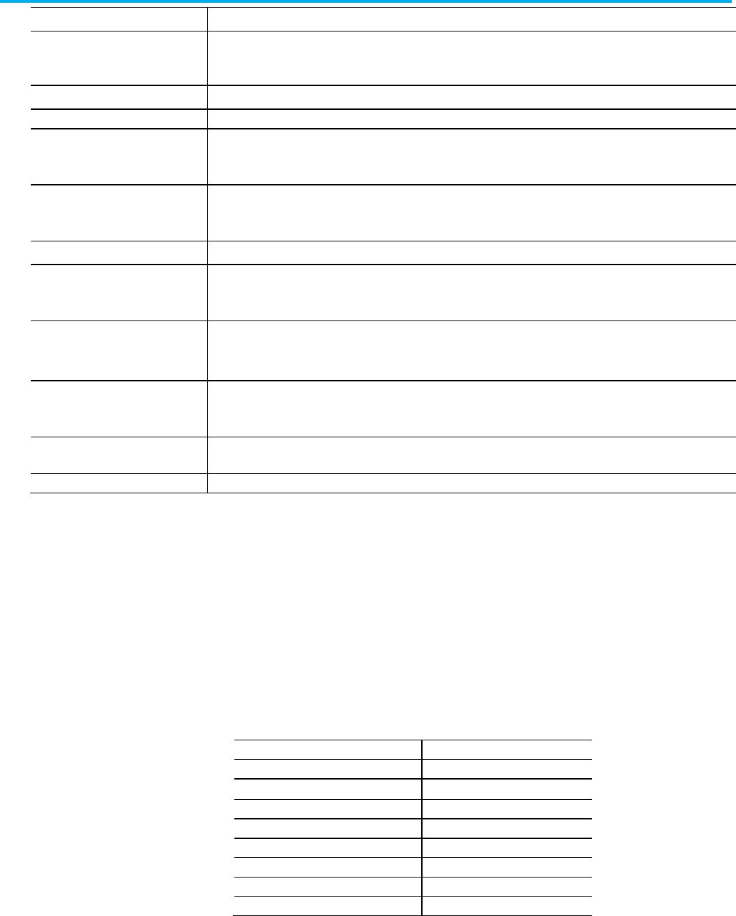
Chapter 4 Define a module component
Publication 1756-RM014B-EN-P - November 2023 77
Attribute
Description
NATActualAddress
The IP address of a safety I/O module or controller specified by the user as the actual address on the network of the
module.
For L5X, this attribute is on the <Port> element.
ConnectorOffset L5X only. This attribute is on the <Port> element.
Width L5X only. This attribute is on the <Port> element.
Size L5X only. This attribute is on the <Bus> element. For a sizable chassis, specify the chassis size.
In L5K, this attribute is the ChassisSize attribute on the MODULE.
Baud L5X only. This attribute is on the <Bus> element. Specify the baud rate (57.6, 115.2, or 230.4).
In L5K, this attribute is the ChABaud or ChBBaud attribute on the MODULE.
ShutdownParentOnFault
Indicates the parent device is shut down when this module faults.
DrivesADCMode Sets or clears the Drives ADC mode bit.
Setting to true on a non-ADC causes the drive to fail.
DrivesADCEnabled
Indicates that Automatic Device Configuration is enabled for this device.
Can be set true only when the DrivesADCMode is set true.
UserDefinedCatalogNumber Used to persist the Catalog Number for drive peripherals.
You do not have to modify this value.
Constant Specify whether the value is a constant value or a dynamic value. For L5K, specify
yes
for a constant value or
no
for a
dynamic value. For L5X, specify true or false.
PermissionSet
Name of the set of permissions, configured in FactoryTalk Security, to apply to this object.
In a safety controller system, the module component for the safety partner
follows the module component for the primary safety controller. All of the
attributes of the safety partner are determined based on those of the primary
safety controller.
The module component for the primary safety controller follows the structure
previously described. The safety partner module uses these attributes:
• Parent
• PortLabel
• ParentModPortID
• Slot
•
CatalogNumber (1756-LSP) •
CompatibleModule
•
Vendor
•
Key
•
ProductType •
Mask
• ProductCode
• SafetyNetwork
• Major
• SafetyEnabled
• Minor
• NATActualAddress
•
Mode
Module attributes in a
safety controller system

Chapter 4 Define a module component
78 Publication 1756-RM014B-EN-P - November 2023
The Module connection consists of the:
• L5X connection structure
• L5K CONNECTION structure
• Connection elements
• Module connection attributes
• Module connection attributes in a safety controller system
• Module guidelines
• Examples
Refer to the L5K connection structure.
<Connections>
<Connection [Connection_Attributes]>
<InputTag>
data
</InputTag>
<OutputTag>
data
</OututTag>
</Connection>
<RackConnection [RackConnection_Attributes]>
<InAliasTag>
data
</InAliasTag>
<OutAliasTag>
data
</OutAliasTag>
</RackConnection>
</Connections>
Refer to this L5K CONNECTION structure.
CONNECTION <connection_name> [(Connection_Attributes)]
[InputData := <value_list>;]
[InputForceData := <value_list>;]
[OutputData := <value_list>;]
[OutputForceData := <value_list>;]
END_CONNECTION
Module connection
L5X connection structure
L5K CONNECTION structure
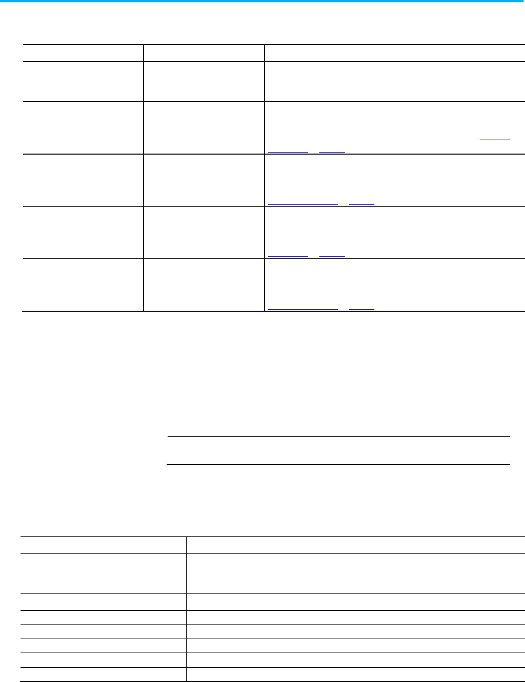
Chapter 4 Define a module component
Publication 1756-RM014B-EN-P - November 2023 79
See the table for .L5X and .L5K items and descriptions.
L5X Item
L5K Item
Description
N/A connection_name The name of the connection.
In L5X, use a Name attribute on the <Connection> element.
InputTag or InputData InputData Input channel data.
In L5X, the data for the input tag is defined with <Data> elements. See Chapter 1
Data Formats on page 43 for more information.
InputTag or InputData InputForceData Forcing information for the input channel.
In L5X, the force data for the input tag is defined with <ForceData> elements. See
Chapter 1 Data Formats on page 43 for more information.
OutputTag or OutputData OutputData Output channel data.
In L5X, the data for the output tag is defined with <Data> elements. See Chapter 1,
Data Formats on page 43 for more information.
OutputTag or OutputData OutputForceData Forcing information for the output channel.
In L5X, the force data for the output tag is defined with <ForceData> elements. See
Chapter 1 Data Formats on page 43 for more information.
For details on the data in the connection list, see the user manual for the I/O
module. The connection list data depends on the I/O module and the
configuration for that module.
In L5K format, forces appear as arrays of bytes under the InputForceData and
OutputForceData attributes of the connection list. In L5X format, forces
appear as arrays of bytes under the <ForceData> elements in the <InputTag>
and <OutputTag> elements.
IMPORTANT
Do not modify forces in the import/export file. Use the programming software to enter
and enable forces.
Refer to these module connection attributes and descriptions.
Attribute
Description
Name
L5X only. Specify the name of the connection.
In L5K, the name is an element of the statement.
Rate L5K only. Specify the requested packet interval (RPI) rate in microseconds.
RPI L5X only. Specify the requested packet interval rate in microseconds.
InputCxnPoint
Specify the input connection point for the primary connection (0...255).
InputSize
Specify the input size (0...255).
OutputCxnPoint Specify the output connection point for the primary connection (0...255).
OutputSize Specify the output size (0...255).
Connection elements
Module connection
attributes

Chapter 4 Define a module component
80 Publication 1756-RM014B-EN-P - November 2023
Attribute
Description
Unicast
Specify if the EtherNet/IP connection is unicast. For L5K, specify yes for unicast or no to remain multicast. For
L5X, specify
true
or
false
.
On export, only appears if the path to the unicast supported I/O module crosses an EtherNet/IP network.
EventID Specify the event ID if used in conjunction with an event task.
ControlNetScheduled Specify how the connection is scheduled. Specify
yes
to schedule over ControlNet or
no
to connect
unscheduled. This attribute is only used if the path from the module to the controller uses ControlNet. For L5X
format specify
true
or
false
.
Type L5X only. Specify the type of connection:
Input
,
Output
,
MotionSync
,
MotionAsync
,
MotionEvent
,
SafetyInput
,
or
SafetyOutput
.
Priority Indicates the rank of the input production.
Valid values = Scheduled (default) or High.
InputConnectionType Indicates the type of input production.
Valid values = Multicast (default) or Unicast.
OutputRedundantOwner Indicates if the output production is a redundant owner.
InputProductionTrigger Indicates the input production trigger.
Valid values = Cyclic, COS, or Application.
ConnectionPath Indicates the target connection path.
InputTagSuffix
Identifies the suffix for the Input Tag.
OutputTagSuffix
Identifies the suffix for the Output Tag
A module connection in a safety controller system has these attributes, in
addition to the module connection attributes previously described.
Attribute
Description
TimeoutMultiplier Specify the timeout multiplier (default = 2) for a safety controller system. This value determines the RPIs of
time to wait for a packet before declaring a time out. This translates into the number of messages that may be
lost before declaring a connection error. A Timeout Multiplier of 1 indicates that no messages may be lost; that
is, there must be a packet every RPI. A Timeout Multiplier of 2 indicates that 1 message may be lost; that is, as
long as a packet is seen in 2 times the RPI, no time-out will occur. Type a number from 1...4.
NetworkDelayMultiplier Specify the network delay multiplier (default = 100%) for a safety controller control system. This value lets you
reduce or increase the connection reaction time limit in cases where the transport time of the message is
significantly less or more than the RPI. This may be the case when the RPI of an output connection is the same
as a lengthy task period. Type a percentage from 10...600.
ReactionTimeLimit Specify the connection reaction time limit (0...5500032) for a safety controller system. The Logix Designer
application calculates the connection reaction time limit as a function of the RPI, timeout multiplier, and
network delay multiplier. The connection reaction time limit is automatically recalculated if any of the values
change.
MaxObservedNetworkDelay L5X only. The MaxObservedNetworkDelay is a measure of the longest time data for a safety connection is
delayed from transporting the safety packets over the network. This attribute is exported for informational
purposes only and is ignored on import.
Observe these guidelines when defining a module.
• Attributes can be in any order. They export in the order defined.
Module connection
attributes in a safety
controller system
Module guidelines
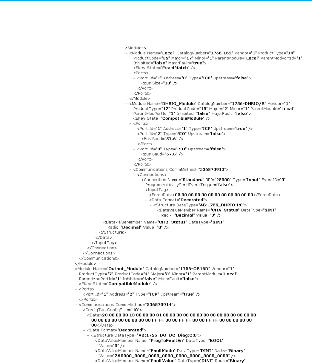
Chapter 4 Define a module component
Publication 1756-RM014B-EN-P - November 2023 81
• A parent module must be defined before any definitions of its
child modules.
L5X module example
Module component
examples
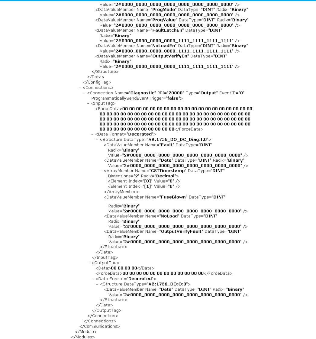
Chapter 4 Define a module component
82 Publication 1756-RM014B-EN-P - November 2023
L5X Safety Partner Module Example
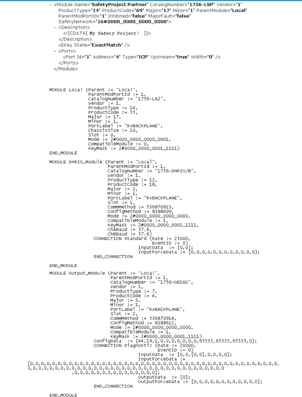
Chapter 4 Define a module component
Publication 1756-RM014B-EN-P - November 2023 83
L5K MODULE example
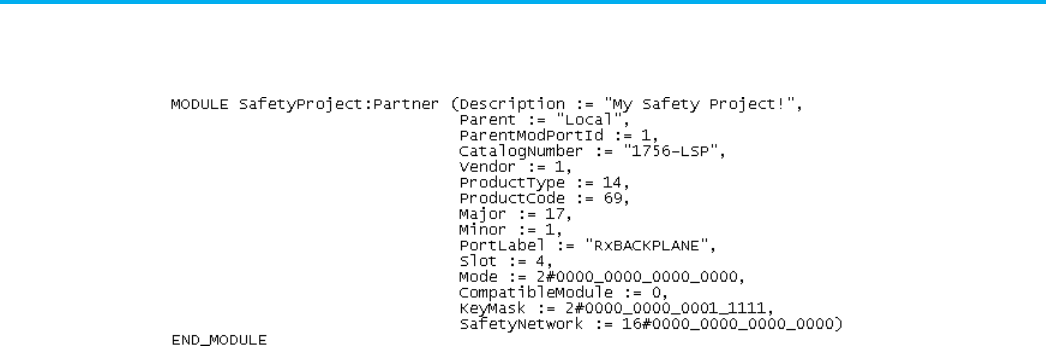
Chapter 4 Define a module component
84 Publication 1756-RM014B-EN-P - November 2023
L5K Safety Partner MODULE example

Publication 1756-RM014B-EN-P - November 2023 85
Chapter 5
Define an Add-On Instruction component
This chapter explains the overall structure of the Add-On Instruction
component.
An Add-On Instruction component defines an Add-On Instruction.
IMPORTANT
The EditedDate attribute of an Add-On Instruction must be updated if the Add-On
Instruction is modified by editing an .L5K or .L5X file.
When you change an Add-On Instruction by manually editing an .L5X file using a text
editor and you do not change the EditedDate attribute, the application does not
overwrite the Add-On Instruction when you import the file.
Refer to the L5K Add-On Instruction Definition structure.
<AddOnInstructionDefinitions>
<AddOnInstructionDefinition
[AddOnInstructionDefinition_Attributes]>
<Description>
<![CDATA[ text ]]>
</Description>
<AdditionalHelpText>
<![CDATA[ text ]]>
</AdditionalHelpText>
<SignatureHistory>
[history]
</SignatureHistory>
<Parameters>
[parameter]
</Parameters>
<LocalTags>
[local_tag]
</LocalTags>
<Routines>
[routine]
</Routine>
<ScanModeRoutine>
Add-On Instruction
component introduction
Add-On Instruction
component
L5X
AddOnInstructionDefinition
Structure
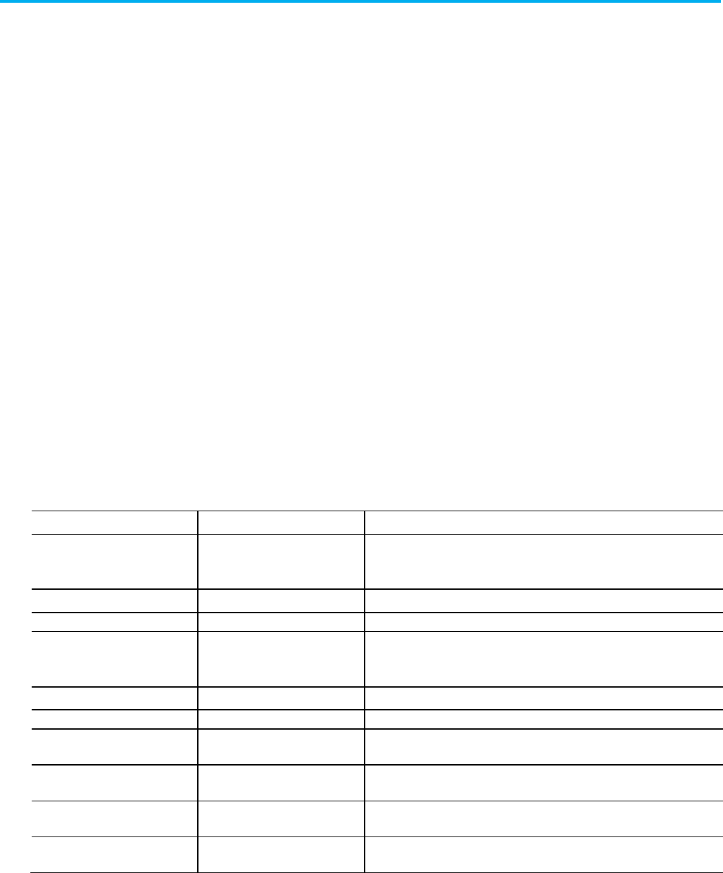
Chapter 5 Define an Add-On Instruction component
86 Publication 1756-RM014B-EN-P - November 2023
[routine]
</ScanModeRoutine>
</AddOnInstructionDefintion>
</AddOnInstructionDefinitions>
Refer to this L5K ADD_On_INSTRUCTION_DEFINITION structure.
ADD_ON_INSTRUCTION_DEFINITION <name>
[(Description := "text", Attributes)]
[<HISTORY_ENTRY declaration>]
[<PARAMETERS declaration>]
[<LOCAL_TAGS declaration>]
[<add_on_instruction_routines]
[<scan_mode_routine>]
END_ADD_ON_INSTRUCTION_DEFINITION
This table contains Add-On Instruction elements nd descriptions for L5X and
L5K items.
L5X Item
L5K Item
Description
N/A name In L5K, the name of the Add-On Instruction.
In L5X, use a Name attribute on the <AddOnInstructionDefinition> element.
Description Description User information about the Add-On Instruction (128 characters maximum).
SignatureHistory HISTORY_ENTRY Optional element for a sealed Add-On Instruction.
AdditionalHelpText N/A In L5K, use the AdditonalHelpText attribute.
For L5X, specify help text for the user help on the Add-On Instruction.
Parameters PARAMETERS Parameters of the Add-On Instruction.
LocalTags LOCAL_TAGS Local tags of the Add-On Instruction.
Routines add_on_instruction_
routines
Logic that comprises the Add-On Instruction. Logic can be relay ladder, function
block, or structured text.
ScanModeRoutine SCAN_MODE_ROUTINE Optional element that has the logic for a Prescan routine, Postscan routine, or
EnableInFalse routine.
EncryptionInfo
ENCRYPTION_INFO
Details of the license based source protection for the lockable object. Only exists for
protected Add-On Instructions exported in plain text.
EncryptedAOIContent
N/A
Source-protected and locked Add-On Instruction content. Only exists for locked
Add-On Instructions exported in plain text.
L5K
ADD_ON_INSTRUCTION_DEFI
NITION structure
Add-On Instruction
elements
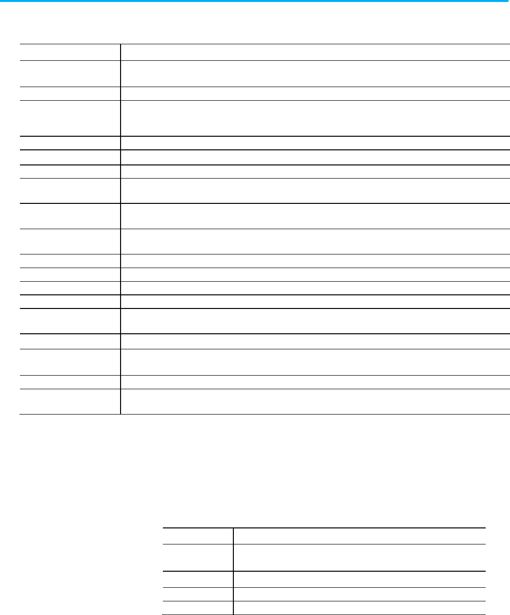
Chapter 5 Define an Add-On Instruction component
Publication 1756-RM014B-EN-P - November 2023 87
This table contains Add-On Instructions attributes.
Attribute
Description
Name L5X only. Specify the name of the Add-On Instruction component.
In L5K, the name is an element of the statement.
Class
Specify the class of the Add-On Instruction. This attribute applies only to safety projects. Type Standard or Safety.
Revision
Specify the revision of the Add-On Instruction, in the form of MajorRevision.MinorRevision. Each revision number can be 1...65,535. If
there is no period, the number is treated as a major revision only.
RevisionExtension
Provide additional information about the revision (40 characters maximum).
RevisionNote Provide information about the revision (128 characters maximum).
Vendor Specify the name of the vendor (40 characters maximum) of the Add-On Instruction.
ExecutePrescan Specify whether to execute the Prescan routine after the Logic is prescanned. Type
1
for yes; type
0
for no. The default is 1 if a
Prescan routine exists.
ExecutePostscan Specify whether to execute the Postscan routine after the Logic is postscanned. Type
1
for yes; type
0
for no. The default is 1 if a
Postscan routine exists.
ExecuteEnableInFalse Specify whether to execute the EnableInFalse routine when enable is false. Type
1
for yes; type
0
for no. The default is 1 if an
EnableInFalse routine exists.
CreatedDate
Specify the date the Add-On Instruction was created.
CreatedBy
Specify the developer that created the Add-On Instruction.
EditedDate
Specify the date the Add-On Instruction was last edited.
EditedBy Specify the developer that edited the Add-On Instruction.
SoftwareRevision Specify the revision of the application last used to edit the Add-On Instruction. The default is the currently open version of the
application.
AdditionalHelpText Specify help text specific to the Add-On Instruction.
PermissionSet Name of the set of permissions, configured in FactoryTalk Security, to apply to this object.
IsEncrypted
Indicates whether the Add-On Instruction is protected with license-based Source Protection and locked.
TrackingGroups The group of tracked objects to which this item belongs. Components can be marked for tracking to determine whether they have
been changed. Version 30 of the Logix Designer application supports only one tracking group.
Enter routines in an Add-On Instruction the same as logic routines. The logic
in a single routine must all be in the same programming language, but each
routine can be in a different programming language. Program the routines in
ladder logic (ROUTINE), function block (FBD_ROUTINE), or structured text
(ST_ROUTINE) languages. The Add-On Instruction has predefined routine
names that you must use and cannot change.
Routine Name
Description
Logic
Defines the logic for the Add-On Instruction.
At the minimum, every Add-On Instruction must have a Logic routine.
Prescan Defines logic to execute during prescan.
Postscan
Defines logic to execute during postscan.
EnableInFalse
Defines logic to execute when EnableIn is false.
For example, this structure for an Add-On Instruction uses all four routines.
ADD_ON_INSTRUCTION_DEFINITION Example (attributes)
PARAMETERS
Add-On Instruction
attributes
Routines in Add-On
Instructions

Chapter 5 Define an Add-On Instruction component
88 Publication 1756-RM014B-EN-P - November 2023
add_on_instruction_parameters
END_PARAMETERS
LOCAL_TAGS
add_on_instruction_local_tags
END_LOCAL_TAGS
FBD_ROUTINE Logic (attributes)
function_block_routine_logic
END_FBD_ROUTINE
ST_ROUTINE Prescan (attributes)
structured_text_routine_logic
END_ST_ROUTINE
ROUTINE Postscan (attributes)
ladder_logic_routine_logic
END_ROUTINE
FBD_ROUTINE EnableInFalse (attributes)
function_block_routine_logic
END_FBD_ROUTINE
END_ADD_ON_INSTRUCTION_DEFINITION
If a tag in an Add-On Instruction references a second Add-On Instruction
whose definition is also present in the file, the referenced Add-On Instruction
definition must appear before the first one in the import/export file.
The parameter component defines Input, Output, and InOut type parameters
in the Add-On Instruction. For L5X format, the default data for the local tag is
defined with a <DefaultData>. The <DefaultData> element is defined the
same as a <Data> element. See Chapter 1 Data Formats on page 43 for more
information on the <Data> element format.
The system defined EnableIn input parameter and EnableOut output
parameter are defined in the export format so the description may be
modified in a .L5K or .L5X format file. The rest of the attributes for the
EnableIn and EnableOut parameters that are system defined will be ignored
by import even though they are present in the import file.
Refer to the L5X parameter structure.
<Parameters>
<Parameter [Parameter_Attributes]>
<Description>
<![CDATA[ text ]] >
</Description>
Parameters
L5X parameters structure

Chapter 5 Define an Add-On Instruction component
Publication 1756-RM014B-EN-P - November 2023 89
<Comments>
<Comment Operand="specifier">
<![CDATA[ comment_text ]]>
</Comment>
</Comments>
<EngineeringUnits>
<EngineeringUnit Operand="specifier">
<![CDATA[ engineering_unit_text ]]>
</EngineeringUnit>
</EngineeringUnits>
<Mins>
<Min Operand="specifier"> min_value </Min>
</Mins>
<Maxes>
<Max Operand="specifier"> max_value </Max>
</Maxes>
<State0s>
<State0 Operand="specifier">
<![CDATA[ state0_text ]]>
</State0>
</State0s>
<State1s>
<State1 Operand="specifier">
<![CDATA[ state1_text ]]>
</State1>
</State1s>
<DefaultData [DefaultData_Attributes]>
data
</DefaultData>
</Parameter>
</Parameters>
Refer to the L5K parameters structure.
PARAMETERS
<name> : <datatype[array_specification]>[(Description
:= "text",
Comment := "text",
EngineeringUnit := "text",
Max := value,
Min := value,
State0 := "text",
State1 := "text",
Parameter_Attributes)];
L5K parameters structure

Chapter 5 Define an Add-On Instruction component
90 Publication 1756-RM014B-EN-P - November 2023
END_PARAMETERS
Refer to the L5X and L5K parameter elements and descriptions.
L5X Item
L5K Item
Description
N/A
name
The name of the parameter.
In L5X, use a Name attribute on the <Parameter> element.
N/A
datatype
Data type of the parameter.
InOut parameters can be atomic (SINT, INT, DINT, and REAL) and compound
(user-defined and array) data types. Input and Output parameters can be only
atomic (SINT, INT, DINT, and REAL) data types.
In L5X, use a DataType attribute on the <Parameter> element.
N/A
array_specification
Dimensional boundaries for an InOut parameter array.
In L5X, use a Dimensions attribute on the <Parameter> element.
Description Description User information about the parameter with a 128-character maximum.
DefaultData N/A The default data values for Input parameters or Output parameters.
In L5K, use a DefaultData attribute.
Comment Comment (optional) User information about specified sub-regions of the parameter.
Can specify Comment<
specifier
>
Where the specifier is:
.bitnumber -
for a bit in the parameter
[element] -
for an array element of the parameter
.membername -
for a structure member of the parameter
There can be multiple comment elements.
EngineeringUnit EngineeringUnit (optional) User specified description of what the unit of the value is (that is, feet,
gallons, kilos).
Can specify EngineeringUnit <
specifier
>
Where the specifier is:
.bitnumber -
for a bit in the parameter
[element] -
for an array element of the parameter
.membername -
for a structure member of the parameter
There can be multiple engineering unit elements.
Max Max (optional) User specified maximum value about qualified sub-regions of the
parameter. Only valid for a parameter’s sub-regions, which is a non-Boolean atomic
datatypes.
Can specify Max <
specifier
>
Where the specifier is:
.bitnumber -
for a bit in the parameter
[element] -
for an array element of the parameter
.membername -
for a structure member of the parameter
There can be multiple max elements.
Parameter elements

Chapter 5 Define an Add-On Instruction component
Publication 1756-RM014B-EN-P - November 2023 91
L5X Item
L5K Item
Description
Min
Min
(optional) User specified minimum value about qualified sub-regions of the
parameter. Only valid for a parameter’s sub-regions, which is a non-Boolean atomic
datatypes.
Can specify Min <
specifier
>
Where the specifier is:
.bitnumber -
for a bit in the parameter
[element] -
for an array element of the parameter
.membername -
for a structure member of the parameter
There can be multiple min elements.
State0 State0 (optional) for Boolean parameters or sub-regions only. User specified description of
what the Zero state of the Boolean value is.
Can specify State0 <
specifier
>
Where the specifier is:
.bitnumber -
for a bit in the parameter
[element] -
for an array element of the parameter
.membername -
for a structure member of the parameter
There can be multiple state0 elements.
State1 State1 (optional) for Boolean parameters or sub-regions only. User specified description of
what the One state of the Boolean value is.
Can specify State1 <
specifier
>
Where the specifier is:
.bitnumber -
for a bit in the parameter
[element] -
for an array element of the parameter
.membername -
for a structure member of the parameter
There can be multiple state1 elements.
Refer to the parameters attributes and descriptions.
Attribute
Description
Name
L5X only. Specify the name of the parameter.
In L5K, the name is an element of the statement.
DataType L5X only. Specify the datatype of the parameter.
InOut parameters can be atomic (SINT, INT, DINT, and REAL) , compound (user-defined and array) data types
object backed (MESSAGE, ALARM, etc.). Input and Output parameters can be only atomic (SINT, INT, DINT, and
REAL) data types.
In L5K, the datatype is an element of the statement.
TagType L5X only. Specify
Base
or
Alias
.
AliasFor L5X only. Name of the base tag that the alias parameter references.
Specify LocaTag<specifier>
Where the
specifier
is a bit (.
bitnumber
), array element ([
element
]), or structure member (.
membername
) of
the tag, or any combination such as
[7].Input.0
.
Parameters attributes
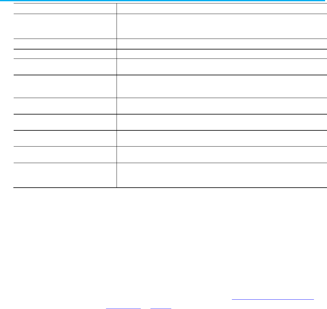
Chapter 5 Define an Add-On Instruction component
92 Publication 1756-RM014B-EN-P - November 2023
Attribute
Description
Dimensions
L5X only. Specify the dimensions of the datatype.
In L5K, the dimensions are an element of the statement.
Usage Specify the type of parameter. Type
Input
,
Output
, or
InOut
.
Radix Specify
decimal
,
hex
,
octal
,
binary
,
exponential
,
float
,
ASCII
.
Required Specify whether the parameter is required. Type
1
if the parameter is required; type
0
if the parameter is
optional.
Constant Specify whether the value for an Input or an Output parameter is a constant value or it can change. For L5K,
specify
yes
for a constant value or
no
for a dynamic value. For L5X, specify
true
or
false
.
ExternalAccess Specify the external access, outside of the controller, to the parameter. Specify
Read/Write
,
Read Only
, or
None.
Max (optional) User specified maximum value for the parameter. Only valid for parameter with non-Boolean atomic
datatype.
Min (optional) User specified minimum value for the parameter. Only valid for parameter with non-Boolean atomic
datatype.
Visible Specify whether the parameter is visible on the display for the instructions. Type
1
if the parameter is visible;
type 0 if the parameter is not visible.
DefaultData L5K only. Specify a default value for the parameter. This attribute is not available if you specify Usage as InOut.
In L5X, the parameter default data is an element of the L5X structure.
The Signature History stores history entries for an Add-On Instruction. There
can be 0…6 entries that are exported in the order they are created. The order
in the file is used during import to store them. If you edit the file manually,
that order is maintained.
• L5K file—The Signature History is stored in the HISTORY_ENTRY
structure.
• L5X file—The Signature History is stored in the <SignatureHistory>
structure.
When an Add-On Instruction is sealed, the Signature History is protected and
hidden in the ENCODED_DATA section. See Encoded/UnencodedAdd-On
Instructions on page 95.
• L5K file—The ENCODED_DATA section is a separate section.
• L5X file—The <EncodedData> section is an element of
<AddOnInstructionDefinitions>.
Refer to the L5X SignatureHistory structure.
<SignatureHistory>
<HistoryEntry [HistoryEntry_Attributes]>
<Description>
<![CDATA[ text ]] >
</Description>
Signature history
L5X SignatureHistory
structure
Chapter 5 Define an Add-On Instruction component
Publication 1756-RM014B-EN-P - November 2023 93
</HistoryEntry>
</SignatureHistory>
Refer to the L5K HISTORY_ENTRY structure.
HISTORY_ENTRY [History_Entry_Attributes)]
END_HISTORY_ENTRY
Refer to the History entry attributes and descriptions.
Attribute
Description
User Specifies the identity of the user that created the entry.
Timestamp
Specifies the timestamp when the entry was created. The value is a UTC date time, such as 2009-04-01T12:08:00.000Z.
SignatureID Specifies the signature ID for the Add-On Instruction when the entry was created. The value is an 8-digit uppercase hex number, such as
8F44EBA3.
Description
User information about the parameter (128 characters maximum).
The local tags component defines local tags in the Add-On Instruction. The
L5K format for defining a local tag is the same format for defining a tag in a
program or at controller scope For more details on defining a tag, see Chapter
6 Defining a Tag Component on page 105. For L5X format, you specify the
default data for the local tag with a <DefaultData> element. Define the
<DefaultData> element the same as a <Data> element. See Chapter 1 Data
Formats on page 43 for more information on the <Data> element format.
Refer to the L5X LocalTags Structure.
<LocalTags>
<LocalTag [LocalTag_Attributes]>
<Description>
<![CDATA[ text ]] >
</Description>
<Comments>
<Comment Operand="specifier">
<![CDATA[ comment_text ]]>
</Comment>
</Comments>
<EngineeringUnits>
<EngineeringUnit Operand="specifier">
<![CDATA[ engineering_unit_text ]]>
</EngineeringUnit>
</EngineeringUnits>
<Mins>
<Min Operand="specifier"> min_value </Min>
L5K HISTORY_ENTRY
structure
History entry attributes
Local tags
L5X LocalTags structure
Chapter 5 Define an Add-On Instruction component
94 Publication 1756-RM014B-EN-P - November 2023
</Mins>
<Maxes>
<Max Operand="specifier"> max_value </Max>
</Maxes>
<State0s>
<State0 Operand="specifier">
<![CDATA[ state0_text ]]>
</State0>
</State0s>
<State1s>
<State1 Operand="specifier">
<![CDATA[ state1_text ]]>
</State1>
</State1s>
<DefaultData [DefaultData_Attributes]>
data
</DefaultData>
</LocalTag>
</LocalTags>
Refer to the L5K LOCAL_TAGS structure.
LOCAL_TAGS
tag_declaration
END_LOCAL_TAGS
Specify these attributes for local tags in L5X format. See Chapter 6 Defining a
Tag Component on page 105 for attributes for local tags in L5K format.
Attribute
Description
Name L5X only. Specify the name of the local tag.
In L5K, the name is an element of the statement.
DataType L5X only. Specify the datatype of the local tag.
Local tags can be atomic (SINT, INT, DINT, and REAL) and compound (for example, user-defined, add-on
instruction defined, array) data types. Local tags cannot be object backed data types (for example, MESSAGE,
ALARM).
In L5K, the datatype is an element of the statement.
Dimensions L5X only. Specify the dimensions of the datatype.
In L5K, the dimensions are an element of the statement.
Radix Specify
decimal
,
hex
,
octal
,
binary
,
exponential
,
float
,
ASCII
.
ExternalAccess
Specify the external access, outside of the controller, to the local tag. Specify Read/Write, Read Only, or None.
Max (optional) User specified maximum value for the local tag. Only valid for local tag with non-Boolean atomic
datatype.
L5K LOCAL_TAGS structure
Local tag attributes
Chapter 5 Define an Add-On Instruction component
Publication 1756-RM014B-EN-P - November 2023 95
Attribute
Description
Min
(optional) User specified minimum value for the local tag. Only valid for local tag with non-Boolean atomic
datatype.
DefaultData
L5K only. Specify a default value for the local tag.
In L5X, the parameter default data is an element of the L5X structure.
These examples are for protected (encoded) and unprotected (clear text)
codes for Add-On Instructions.
If the project contains high-integrity Add-On Instructions, those Add-On
Instructions always appear as encoded data components when you export
the project.
See Exporting Source-protected Logic on page 28 on page 35 for procedures.
Refer to the L5X EncodedData routines structure.
<EncodedData EncodedType= "type", Name="name",
Type="routinetype"
[,other_attributes]>
<Description>
<![CDATA[ text ]] >
</Description>
encoded_data
</EncodedData>
Refer to the L5K ENCODED_DATA routines structure.
ENCODED_DATA [( EncodedType: type, Name:= name,
Type:= routinetype,
other_attributes)]
encoded_data
END_ENCODED_DATA
See the table for encoded data attributes for .L5X and .L5K items and their
descriptions.
L5X Item
L5K Item
Description
type
type
The type of data encoded.
In L5K, specify
ADD_ON_INSTRUCTION_DEFINITION
In L5X, specify
AddOnInstructionDefinition
name
name
The name of the protected Add-On Instruction.
SignatureID
SignatureID
32-bit value based upon the current configuration of the Add-On-Instruction.
Encoded/Unencoded
Add-On Instructions
L5X EncodedData Structure
L5K ENCODED_DATA
Structure
Encoded data attributes
Chapter 5 Define an Add-On Instruction component
96 Publication 1756-RM014B-EN-P - November 2023
L5X Item
L5K Item
Description
SignatureTimestamp
SignatureTimestamp
The time and date that the Add-On-Instruction was sealed.
SafetySignatureID
SafetySignatureID
Only applies to Safety Add-On-Instructions. Additional safety ID calculated online in
the safety system.
N/A
other_attributes
Attributes of the Add-On Instruction that are not protected during export.
N/A
encoded_data
The protected portion of the Add-On Instruction.
IsEncrypted
IsEncrypted
Indicates whether the Add-On Instruction is protected with license-based Source
Protection and locked.
IMPORTANT
When the Add-On Instruction is source-protected, the
encoded_data
information is
encrypted. If you modify this encrypted information, you cannot re-import the Add-On
Instruction.
See the table for the encoded information element for the .L5X and .L5K item
and identifier.
L5X Item
L5K Item
Identifies
EncryptionKey
ENCRYPTION_KEY
Identifies the options the user has chosen for protecting and locking their content.
See the table for encoded key attributes and their descriptions.
Attribute
Description
Name Identifies the type of protection.
ID
Identifier for the key (Firm code, product code).
Description Description of what the key is associated with (license name).
Vendor
Indicates the vendor who supplied the key.
PublicKey
Stores the public key that will be used for the locking of the associated object.
This table contains encoded content attributes and their descriptions.
Attribute
Description
EncryptedType Indicates the underlying language of the routine for this encoded content (for example, RLL or Structured text).
OnlineEditType L5X only. Specify the online edit logic type (
Original
,
PendingEdits
, or
TestEdits
). This attribute is not specified if
there are no edits.
Encoded Information
elements
Encoded key attributes
Encoded content attributes
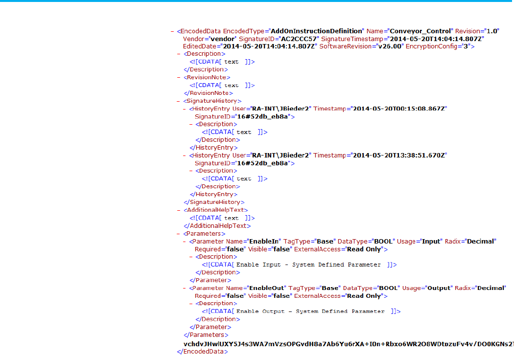
Chapter 5 Define an Add-On Instruction component
Publication 1756-RM014B-EN-P - November 2023 97
Refer to the L5K Encoded Add-On Instruction example.
Refer to the L5K Encoded Add-On Instruction example.
ENCODED_DATA (EncodedType :=
ADD_ON_INSTRUCTION_DEFINITION,
Name := "Conveyor_Control",
Description := "This is the description",
Revision := "1.0",
RevisionNote := "This is a Revision Note",
Vendor := "vendor",
SignatureID := AC2CCC57,
SignatureTimestamp :=
"2014-05-20T14:04:14.807Z",
EditedDate := "2014-05-20T14:04:14.807Z",
AdditionalHelpText := "This is help text",
EncryptionConfig := 3)
HISTORY_ENTRY (User := RA-INT\JBieder2,
Timestamp :=
"2014-05-20T00:15:08.867Z",
SignatureID := 16#52db_eb8a,
Description := "History description")
L5X Encoded Add-On
Instruction example
L5K Encoded Add-On
Instruction example

Chapter 5 Define an Add-On Instruction component
98 Publication 1756-RM014B-EN-P - November 2023
END_HISTORY_ENTRY
PARAMETERS
EnableIn : BOOL (Description := "Enable Input -
System Defined Parameter",
Usage := Input,
RADIX := Decimal
Required := No,
Visible := No,
ExternalAccess := Read
Only);
EnableOut : BOOL (Description := "Enable Output
- System Defined Parameter",
Usage := Output,
RADIX := Decimal,
Required := No,
Visible := No,
ExternalAccess := Read
Only);
END_PARAMETERS
5PC4UUeSPrD8+QMe30neT5/97J+VmK95qgOApHiZ7VpmkuGyeYVm
zDm3ceYND35YMmzC4xyFQfJYld…
END_ENCODED_DATA
Use these Add-On Instruction guidelines with function blocks:
• If the operand is not a qualified tag or literal value, the Add-On
Instruction is not verified.
• The X and Y grid locations are a relative position from the upper-left
corner of the sheet. X is the horizontal position; Y is the vertical
position.
This L5X file shows a definition partial export example for an L5X Add-On
Instruction.
Add-On Instruction
Guidelines
L5X unencoded
AddOnInstruction definition
example
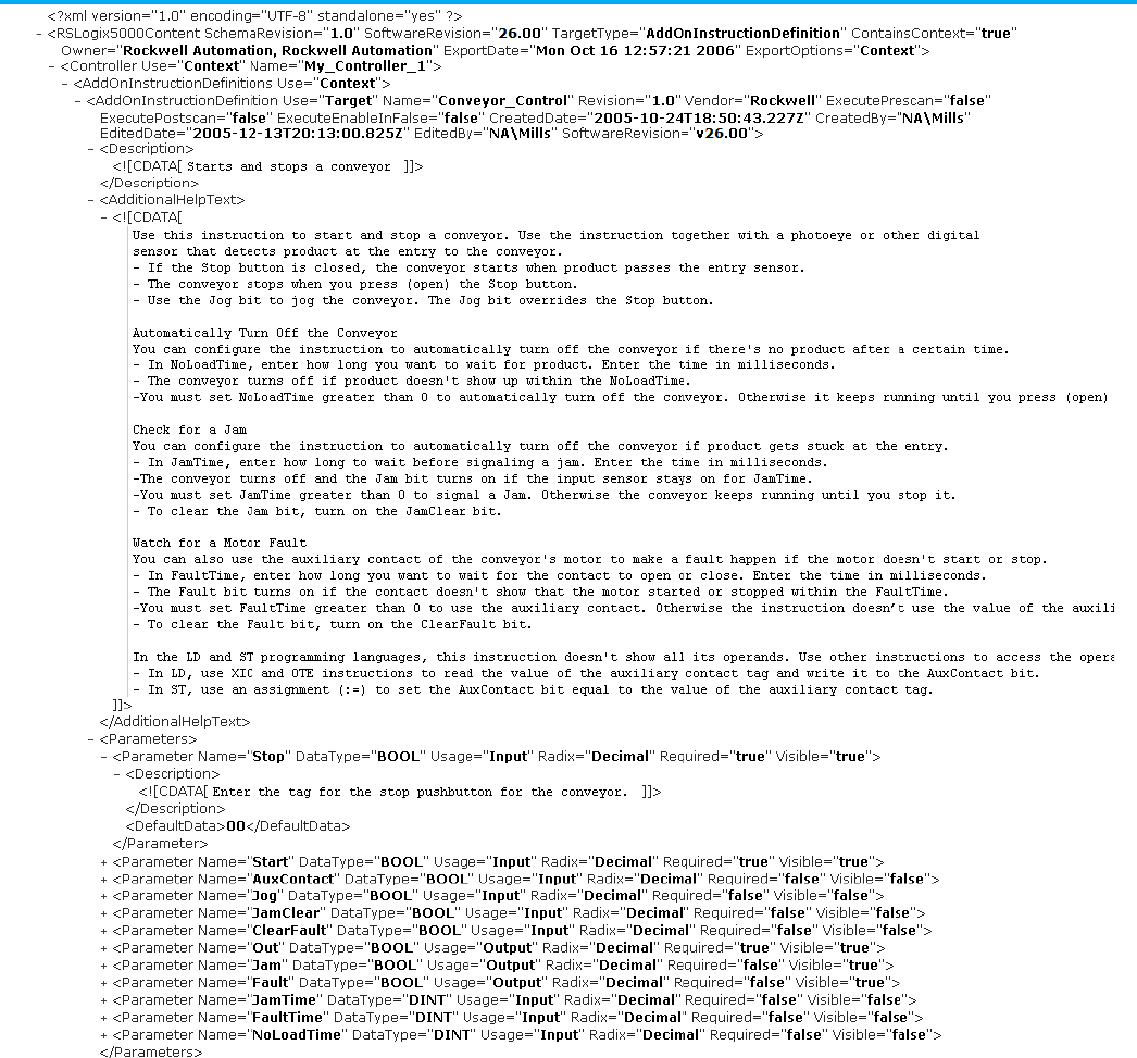
Chapter 5 Define an Add-On Instruction component
Publication 1756-RM014B-EN-P - November 2023 99
Add-On Instruction Example, Continued
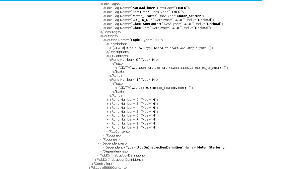
Chapter 5 Define an Add-On Instruction component
100 Publication 1756-RM014B-EN-P - November 2023
Refer to the L5K unencoded ADD_ON_INSTRUCTION_DEFINITION
example.
ADD_ON_INSTRUCTION_DEFINITION Valve (Description :=
"Simple valve control",
Revision := “1.0”, RevisionExtension := “B”,
Vendor := “RaesUDICreationsUnlimited”,
ExecutePrescan := Yes,
ExecutePostscan := No, ExecuteEnableInFalse :=
No,
CreatedBy := “apollo\drjones”, EditedDate :=
“2005-01-05T15:24:59.188Z”,
EditedBy := “apollo\drjones”,
AdditionalHelpText := “My first Add-On
Instruction – how cool!”)
PARAMETERS
Valve_Command : BOOL (Description := “0 - Close
valve$N1 - Open valve”,
Radix := Decimal, Required := Yes, Visible := Yes,
DefaultData := “1”);
Array_Parameter : REAL[5] (Type := InOut, Radix
:= Float, Required := Yes,
Visible := Yes); Valve_Out : DINT (Type := Output,
Radix := Decimal,
L5K unencoded
ADD_ON_INSTRUCTION
_DEFINITION example

Chapter 5 Define an Add-On Instruction component
Publication 1756-RM014B-EN-P - November 2023 101
Required := No, Visible := Yes, DefaultData :=
“0”);
Reset : BOOL (Description := “Used by Prescan
routine to run Reset code”,
Type := Input, Radix := Decimal, Required := No,
Visible := No,
DefaultData := “1”);
END_PARAMETERS
LOCAL_TAGS
Valve_Type : DISCRETE_2STATE (Description :=
“The valve is a 2 state valve”,
DefaultData :=
“[49,0.00000000e+000,0,0,0.00000000e+000,0.00000000e+00
0,
0.00000000e+000,0.00000000e+000,0.00000000e+000,0.00
000000e+000]”);
END_LOCAL_TAGS
FBD_ROUTINE Logic (Description := "This UDI Logic
routine is nonsense but shows the
format sufficiently. In fact, it does not even use the
InOut Parameter",
SheetSize := "Letter (8.5x11in)",
SheetOrientation := Landscape)
SHEET (Name := "")
D2SD_BLOCK (ID := 0, X := 200, Y := 160,
Operand := Valve_Type,
VisiblePins := "ProgCommand,
State0Perm, State1Perm, FB0, FB1,
HandFB, ProgProgReq, ProgOperReq,
ProgOverrideReq, ProgHandReq,
Out, Device0State, Device1State,
CommandStatus, FaultAlarm,
ModeAlarm, ProgOper, Override,
Hand")
END_D2SD_BLOCK
IREF (ID := 1, X := 120, Y := 100, Operand
:= Valve_Command)
END_IREF
OREF (ID := 2, X := 460, Y := 140, Operand
:= Valve_Out)
END_OREF
END_SHEET
END_FBD_ROUTINE
ST_ROUTINE Prescan (Description := "This should run
before the Instruction does")
'//If Reset is True - do something
'IF (Reset) THEN
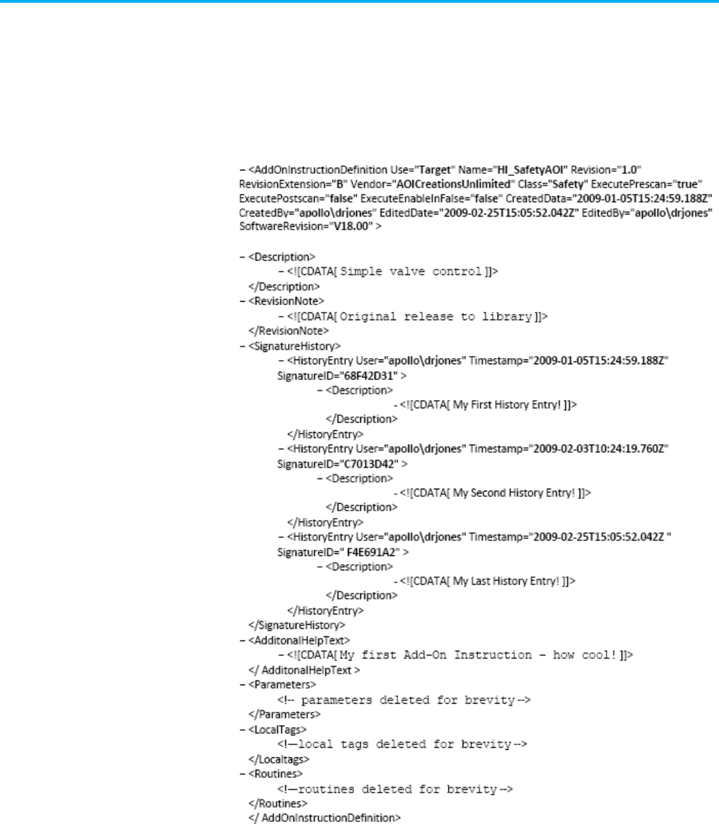
Chapter 5 Define an Add-On Instruction component
102 Publication 1756-RM014B-EN-P - November 2023
' //do something
'END_IF;
'
END_ST_ROUTINE
END_ADD_ON_INSTRUCTION_DEFINITION
Refer to the L5X unencoded safety AddOnInstruction definition example.
Refer to the L5K unencoded safety ADD_ON_INSTRUCTION_DEFINITION
example.
ADD_ON_INSTRUCTION_DEFINITION HI_SafetyAOI (Description
:= "sealed safety AOI",
Revision := “1.0”, RevisionExtension := “B”,
L5X unencoded safety
AddOnInstruction definition
example
L5K unencoded safety
ADD_ON_INSTRUCTION
_DEFINITION example

Chapter 5 Define an Add-On Instruction component
Publication 1756-RM014B-EN-P - November 2023 103
RevisionNote := “Original release to library”,
Vendor := “AOICreationsUnlimited”, Class := Safety,
ExecutePrescan := Yes,
ExecutePostscan := No, ExecuteEnableInFalse := No,
CreatedDate := “2009-01-05T15:24:59.188Z”, CreatedBy
:= “apollo\drjones”,
EditedDate := “2009-02-25T15:05:52.042Z”, EditedBy :=
“apollo\drjones”,
AdditionalHelpText := “My first HI Safety Add-On
Instruction”)
HISTORY_ENTRY (User := “apollo\drjones”,
Timestamp := “2009-01-05T15:24:59.188Z”, SignatureID
:= 68F42D31,
Description := “My First History Entry!”)
END_ HISTORY_ENTRY
HISTORY_ENTRY (User := “apollo\drjones”,
Timestamp := “2009-02-03T10:24:19.760Z”, SignatureID
:= C7013D42,
Description := “My Second History Entry!”)
END_ HISTORY_ENTRY
HISTORY_ENTRY (User := “apollo\drjones”,
Timestamp := “2009-02-25T15:05:52.042Z”, SignatureID
:= F4E691A2,
Description := “My Last History Entry!”)
END_ HISTORY_ENTRY
(* PARAMETERS, LOCAL_TAGS, and ROUTINE blocks deleted for
brevity *)
END_ADD_ON_INSTRUCTION_DEFINITION

Publication 1756-RM014B-EN-P - November 2023 105
Chapter 6
Define a tag component
This chapter explains the overall structure of the tag component.
The tag component defines the tags associated with the logic you selected or
within the program you selected. Within a tag list in the L5K format, message
and motion tags must follow all non-motion tags, and axis tags must follow
motion group tag. Tags may appear in any order in the L5X format.
IMPORTANT
For detailed information about atomic and structure tags and their supported
attributes and ranges, see the Logix5000 Controller Common Procedures Programming
Manual, publication 1756-PM001.
Refer to the L5X tag structure.
<Tag [Tag_Attributes]>
<ConsumeInfo [Consume_Attributes]/>
<ProduceInfo [Produce_Attributes]/>
<Description>
<![CDATA[ text ]]>
</Description>
<Comments>
<Comment Operand="specifier">
<![CDATA[ comment_text ]]>
</Comment>
</Comments>
<EngineeringUnits>
<EngineeringUnit Operand="specifier">
<![CDATA[ engineering_unit_text ]]>
</EngineeringUnit>
</EngineeringUnits>
<Mins>
<Min Operand="specifier"> min_value </Min>
</Mins>
<Maxes>
<Max Operand="specifier"> max_value </Max>
</Maxes>
Tag component
introduction
Tag component
L5X tag structure

Chapter 6 Define a tag component
106 Publication 1756-RM014B-EN-P - November 2023
<State0s>
<State0 Operand="specifier">
<![CDATA[ state0_text ]]>
</State0>
</State0s>
<State1s>
<State1 Operand="specifier">
<![CDATA[ state1_text ]]>
</State1>
</State1s>
<Data>
value
</Data>
<ForceData>
value
</ForceData
</Tag>
Refer to the L5K TAG structure.
<tag_name> [OF alias] : <type["x,y,z"]>
[(Description := "text",
Comment := "text",
Comment := "text",
EngineeringUnit := "text",
Max := value,
Min := value,
State0 := "text",
State1 := "text",
Tag_Attributes,
Produce_Attributes,
Consume_Attributes)]
[, <tag_force_data>] := value;
Refer to the L5X and L5K tag elements attributes and descriptions.
L5X Item
L5K Item
Description
N/A
tag_name
The name of the tag.
In L5X, use a Name attribute on the <Tag> element.
N/A
alias
Name of the base tag that the alias tag references.
Specify
tag
<
specifier
>
Where the
specifier
is a bit (.
bitnumber
), array element ([
element
]), or structure
member (.
membername
) of the tag.
In L5X, use an AliasFor attribute on the <Tag> element.
L5K TAG structure
Tag elements

Chapter 6 Define a tag component
Publication 1756-RM014B-EN-P - November 2023 107
L5X Item
L5K Item
Description
N/A
x, y, z
The number of elements within the array dimension.
For example [5, 10, 2].
In an L5K array tag, there cannot be any white space between the type and array
definition. There must be a space between the tag name and the colon and another
space between that same colon and the type name.
In L5X, use a Dimension attribute on the <Tag> element.
ConsumeInfo N/A Identifies a consumed tag and provides the tag attributes.
In L5K, specify Consume_Attributes attributes .
ProduceInfo
N/A
Identifies a produced tag and provides the tag attributes.
In L5K, specify Produce_Attributes attributes.
Description Description User information about the tag.
Comment Comment Provide information about a tag component.
Can specify Comment<
specifier
>
Where the
specifier
is:
.
bitnumber
for a bit in the tag.
[
element
] for an array element of the tag.
.
membername
for a structure member of the tag.
There can be multiple comment elements.
Data
value
Tag data.
In L5X, this element can also contain additional attributes for other tag types.
EngineeringUnit
EngineeringUnit
(optional) User-specified description of what the unit of the value is, in feet, gallons,
or kilos.
Can specify EngineeringUnit <
specifier
>
Where the
specifier
is:
.bitnumber
- for a bit in the tag
[element]
- for an array element of the tag
.membername
- for a structure member of the tag
There can be multiple engineering unit elements.
Max Max (optional) User-specified maximum value about qualified sub-regions of the
parameter. Only valid for the sub-regions of the parameter, which is a non-Boolean
atomic datatypes.
Can specify EngineeringUnit <
specifier
>
Where the
specifier
is:
.bitnumber
- for a bit in the tag
[element]
- for an array element of the tag
.membername
- for a structure member of the tag
There can be multiple max elements.

Chapter 6 Define a tag component
108 Publication 1756-RM014B-EN-P - November 2023
L5X Item
L5K Item
Description
Min
Min
(optional) User-specified minimum value about qualified sub-regions of the
parameter. Only valid for the sub-regions of the parameter, which is a non-Boolean
atomic datatypes.
Can specify EngineeringUnit <
specifier
>
Where the
specifier
is:
.bitnumber
- for a bit in the tag
[element]
- for an array element of the tag
.membername
- for a structure member of the tag
There can be multiple min elements.
State0 State0 (optional) For Boolean parameters or sub-regions only. User-specified description of
what the Zero state of the Boolean value is.
Can specify EngineeringUnit <
specifier
>
Where the
specifier
is:
.bitnumber
- for a bit in the tag
[element]
- for an array element of the tag
.membername
- for a structure member of the tag
There can be multiple stat0 elements.
State1 State1 (optional) For Boolean parameters (or sub-regions) only. User-specified description
of what the One state of the Boolean value is.
Can specify EngineeringUnit <
specifier
>
Where the
specifier
is:
.bitnumber
- for a bit in the tag
[element]
- for an array element of the tag
.membername
- for a structure member of the tag
There can be multiple state1 elements.
ForceData
tag_force_data
Tag force data.
Refer to the tag attributes and descriptions.
Attribute
Description
Name The name of the tag.
In L5K, the name is an element of the statement.
TagType L5X only. Type
Base
,
Alias
,
Produce
, or
Consumed
.
Tag attributes

Chapter 6 Define a tag component
Publication 1756-RM014B-EN-P - November 2023 109
Attribute
Description
DataType
Type of tag.
Atomic types: BOOL, SINT, INT, DINT, LINT, REAL
String types: STRING
Predefined types such as: AXIS_CONSUMED, AXIS_GENERIC_DRIVE, AXIS_SERVO, AXIS_SERVO_DRIVE,
AXIS_VIRTUAL, CAM, CAM_PROFILE, CONTROL, COORDINATE_SYSTEM, COUNTER, MESSAGE, MOTION_GROUP
Equipment phase types: PHASE, PHASE_INSTRUCTION
Safety types: CONNECTION_STATUS and unique types for each safety instruction
Function block types: unique type for each function block
Sequential function chart: SFC_ACTION, SFC_STEP, SFC_STOP
User-defined data types.
Add-On Instruction defined data types.
Module-defined data types.
AliasFor L5X only. Name of the base tag that the alias tag references.
Specify
tag
<
specifier
>
Where the
specifier
is a bit (.
bitnumber
), array element ([
element
]), or structure member (.
membername
) of the
tag, or any combination such as
[7].Input.0
.
Dimensions L5X only. The number of elements within the array dimension.
For example [5, 10, 2].
Class Specify the class of the tag. This attribute applies only to safety controller projects. Type
Standard
or
Safety
.
Radix
Specify the display style as decimal, hex, octal, binary, exponential, float, ASCII, or date/time. (LINT only).
PLCMappingFile If this tag is mapped to a PLC controller, specify the file number, which can be any positive number.
For L5X, this attribute is on the <ProduceInfo> element.
PLC2Mapping If this tag is mapped to a PLC-2 file, set this attribute to 1. If this tag is not mapped to a PLC-2 file, set this
attribute to 0.
For L5X, this attribute is on the <ProduceInfo> element.
ProgrammaticallySend
EventTrigger
If the project programmatically sends an event trigger, set this attribute to
1
. Otherwise, set this attribute to
0
.
For L5X, this attribute is on the <ProduceInfo> or <ConsumeInfo> element.
Unicast
Allow connections to be unidirectional, rather than bidirectional. Type Yes or No.
UnicastPermitted Specify when unicast connections can be received. Type
Yes
or
No
.
For L5X, this attribute is on the <ProduceInfo> element.
Usage • Specify how an Equipment Phase program uses a tag. This attribute applies only to tags that are
program-scoped to an Equipment Phase program. Type
Input
,
Output
, or
Normal
.
• Specify how a parameter is used. Type
Input
,
Output
,
InOut
, or
Public
.
Sequencing Specify if the parameter can be seen by the FactoryTalk Batch Server. Only Input and Output parameters can
be used by a sequence. Usage is Input or Output.
ExternalAccess
Specify the external access, outside of the controller, to the tag. Specify Read/Write, Read Only, or None.
OpcUaAccess
Specify the level of access (Read Only, Read/Write, or None) that external OPC UA clients have to tags.
Max
(optional) User specified maximum value for the tag. Only valid for tag with non-Boolean atomic datatype.
Min (optional) User specified minimum value for the tag. Only valid for tag with non-Boolean atomic datatype.
Constant Specify whether the tag value is a constant value or it can change. For L5K, specify
yes
for a constant value or
no for a dynamic value. For L5X, specify true or false.
PermissionSet Name of the set of permissions, configured in FactoryTalk Security, to apply to this object.
Chapter 6 Define a tag component
110 Publication 1756-RM014B-EN-P - November 2023
Attribute
Description
TrackingGroups
The group of tracked objects to which this item belongs. Components can be marked for tracking to determine
whether they have been changed. Version 30 of the Logix Designer application supports only one tracking
group.
A produced tag has these attributes, and those for a standard tag.
Attribute
Description
ProduceCount Specify the number of consumers allowed with any positive number.
In L5X, this attribute is on the <ProduceInfo> element.
MinimumRPI Specify the smallest and fastest packet interval at which consumers may consume data from the tag
(0.196...536870.911 and 1...536870.911 for CompactLogix).
MaximumRPI Specify the largest and slowest packet interval at which consumers may consume data from the tag
(0.196...536870.911).
DefaultRPI Specify a default RPI that the produced tag provides value to consumers that attempt to connect with an
out-of-range RPI (0.196...536870.911).
A consumed tag also has these attributes, in addition to those for a standard
tag.
IMPORTANT
If consumed information is provided on an alias tag, the alias tag is converted to a base
tag before it can consume data.
Attribute
Description
Producer If the controller consumes this tag, specify the name of the remote controller that produces this tag. You must also specify RemoteTag
and RPI attributes.
In L5X, this attribute is on the <ConsumeInfo> element.
RemoteTag If the controller consumes this tag from a controller that supports tag names, specify the name of the tag on the remote controller. You
must also specify Producer and RPI attributes.
In L5X, this attribute is on the <ConsumeInfo> element.
RemoteFile If the controller consumes this tag from a PLC-5 controller, specify the PLC-5 file number, as any positive number, on the PLC-5
controller. You must also specify Producer and RPI attributes.
In L5X, this attribute is on the <ConsumeInfo> element.
RPI If the controller consumes this tag, specify the RPI value in milliseconds, as any positive number. You must also specify Producer and
RemoteTag attributes.
In L5X, this attribute is on the <ConsumeInfo> element.
The ALARM_ANALOG tag consists of the:
• L5X tag structure for ALARM_ANALOG tag
• L5K tag structure for ALARM_ANALOG tag
• ALARM_ANALOG tag attributes
Produced tag attributes
Consumed tag attributes
ALARM_ANALOG tag

Chapter 6 Define a tag component
Publication 1756-RM014B-EN-P - November 2023 111
In an .L5X file, tag attributes for an ALARM_ANALOG tag are in the Data
element.
<Data Format="Alarm">
<AlarmAnalogParameters [Alarm_Analog_Attributes]/>
<AlarmConfig>
messages
alarm_class
HMI_command
</AlarmConfig>
</Data>
In an .L5K file, tag attributes for an ALARM_ANALOG tag are in the tag
statement.
<tag_name> : <type>
[(Alarm_Analog_Attributes)]
See the table for ALARM_ANALOG tag attributes and their descriptions.
Attribute
Description
EnableIn Specify whether to enable the alarm tag. Type
0
to disable the tag; type
1
to enable the tag.
InFault
Specify the quality of the input fault data. Type 1 for bad quality; type 0 for good quality.
HHEnabled
Specify the whether the alarm monitors for a high-high limit. Type 1 to enable; type 0 to disable.
HEnabled Specify the whether the alarms monitors for a high limit. Type
1
to enable; type
0
to disable.
LEnabled
Specify the whether the alarm monitors for a low limit. Type 1 to enable; type 0 to disable.
LLEnabled
Specify the whether the alarms monitors for a low-low limit. Type 1 to enable; type 0 to disable.
AckRequired
Specify whether the alarms requires acknowledgment. Type 1 to enable; type 0 to disable.
ProgAckAll Specify whether the program acknowledges all alarm conditions. Type
1
to enable; type
0
to disable.
OperAckAll
Specify whether an operator acknowledges all alarm conditions. Type 1 to enable; type 0 to disable.
HHProgAck
Specify whether the program acknowledges a high-high condition. Type 1 to enable; type 0 to disable.
HHOperAck
Specify whether an operator acknowledges a high-high condition. Type 1 to enable; type 0 to disable.
HProgAck Specify whether the program acknowledges a high condition. Type
1
to enable; type
0
to disable.
HOperAck Specify whether an operator acknowledges a high condition. Type
1
to enable; type
0
to disable.
LProgAck
Specify whether the program acknowledges a low condition. Type 1 to enable; type 0 to disable.
LOperAck
Specify whether an operator acknowledges a low condition. Type 1 to enable; type 0 to disable.
LLProgAck Specify whether the program acknowledges a low-low condition. Type
1
to enable; type
0
to disable.
LLOperAck
Specify whether an operator acknowledges a low-low condition. Type 1 for enabled; type 0 for disabled.
HHOperShelve
Set by the operator to shelve a high-high condition.
HOperShelve
Set by the operator to shelve a high condition.
LOperShelve
Set by the operator to shelve a low condition.
LLOperShelve
Set by the operator to shelve a low-low condition.
ROCPosProgAck Specify whether the program acknowledges a positive (increasing), rate-of-change condition. Type
1
to enable; type
0
to
disable.
ROCPosOperAck
Specify whether an operator acknowledges a positive (increasing), rate-of-change condition. Type 1 to enable; type 0 to
disable.
ROCPNegProgAck Specify whether the program acknowledges a negative (decreasing), rate-of-change condition. Type
1
to enable; type
0
to
disable.
L5X tag structure for
ALARM_ANALOG tag
L5K tag structure for
ALARM_ANALOG tag
ALARM_ANALOG tag
attributes

Chapter 6 Define a tag component
112 Publication 1756-RM014B-EN-P - November 2023
Attribute
Description
ROCPNegOperAck
Specify whether an operator acknowledges a negative (decreasing), rate-of-change condition. Type 1 to enable; type 0 to
disable.
ROCPosOperShelve
Set by the operator to shelve a positive rate-of-change condition.
ROCNegOperShelve
Set by the operator to shelve a negative rate-of-change condition.
ProgSuppress
Specify whether the program can suppress an alarm. Type 1 to enable; type 0 to disable.
OperSuppress
Specify whether an operator can suppress an alarm. Type 1 to enable; type 0 to disable.
ProgUnsuppress Specify whether the program can unsuppress an alarm. Type
1
to enable; type
0
to disable.
OperUnsuppress
Specify whether an operator can unsuppress an alarm. Type 1 to enable; type 0 to disable.
ProgDisable Specify whether the program disables an alarm. Type
1
to enable; type
0
to disable.
OperDisable
Specify whether an operator disables an alarm. Type 1 to enable; type 0 to disable.
ProgEnable
Specify whether the program enables an alarm. Type 1 to enable; Type 0 to disable.
OperEnable
Specify whether an operator enables an alarm. Type 1 to enable; type 0 to disable.
ProgUnshelveAll
Set by the user program to unshelve all conditions on this alarm.
AlarmCountReset
Specify whether to reset the alarm count. Type 1 to reset; type 0 to not reset.
In
Specify the analog input (REAL) to the alarm.
HHLimit
Specify the high-high limit (REAL) for the alarm condition.
HHSeverity
Specify the severity (1...500) of a high-high alarm condition.
HLimit
Specify the high limit (REAL) for the alarm condition.
HSeverity
Specify the severity (1...500) of a high alarm condition.
LLimit
Specify the low limit (REAL) for the alarm condition.
LSeverity
Specify the severity (1...500) of a low alarm condition.
LLLimit
Specify the low-low limit (REAL) for the alarm condition.
LLSeverity
Specify the severity (1...500) of a low-low alarm condition.
HHOperUnshelve Set by the operator to unshelve a high-high condition.
HOperUnshelve Set by the operator to unshelve a high condition.
LOperUnshelve
Set by the operator to unshelve a low condition.
LLOperUnshelve
Set by the operator to unshelve a low-low condition.
MinDurationPRE
Specify the minimum time (DINT) an alarm condition to remain true for the alarm to be considered active.
HHMinDurationEnable Set to enable minimum duration timer when detecting the high-high condition.
HMinDurationEnable Set to enable minimum duration timer when detecting the high condition.
LMinDurationEnable
Set to enable minimum duration timer when detecting the low condition.
LLMinDurationEnable
Set to enable minimum duration timer when detecting the low-low condition.
Deadband
Specify the deadband (REAL) for the high-high, high, low, and low-low levels.
ROCPosLimit
Specify the positive rate-of-change limit (REAL) for the alarm condition.
ROCPosSeverity Specify the severity (1...500) of a positive rate-of-change alarm condition.
ROCNegLimit Specify the negative rate-of-change limit (REAL) for the alarm condition.
ROCNegSeverity
Specify the severity (1...500) of a negative rate-of-change alarm condition.
ROCPeriod
Specify the time period (seconds) to evaluate rate-of-change conditions.
ROCPosOperUnshelve Set by the operator to unshelve a positive rate-of-change condition.
ROCNegOperUnshelve
Set by the operator to unshelve a negative rate-of-change condition.
ShelveDuration
Time duration for which a shelved alarm will be shelved, between 1 and
MaxShelveDuration
.
MaxShelveDuration
Maximum time duration for which an alarm can be shelved.
AssocTag1
Specify a tag associated with the alarm.
AssocTag2
Specify a tag associated with the alarm.
AssocTag3 Specify a tag associated with the alarm.
AssocTag4 Specify a tag associated with the alarm.

Chapter 6 Define a tag component
Publication 1756-RM014B-EN-P - November 2023 113
Attribute
Description
AlarmClass
Specify an alarm class for the alarm.
In L5X, use an AlarmClass element in the Data Element.
HMICmd Specify a command string for the HMI.
In L5X, use an HMICommand element in the Data Element.
The ALARM_DIGITAL tag consists of the:
• L5X tag structure for ALARM_DIGITAL tag
• L5K tag structure for an ALARM_DIGITAL tag
• ALARM_DIGITAL tag
In an .L5X file, tag attributes for an ALARM_DIGITAL tag are in the Data
element.
<Data Format="Alarm">
<AlarmDigitalParameters [Alarm_Digital_Attributes]/>
<AlarmConfig>
message
alarm_class
HMI_command
</AlarmConfig>
</Data>
In an .L5K file, tag attributes for an ALARM_DIGITAL tag are in the tag
statement.
<tag_name> : <type>
[(Alarm_Digital_Attributes)] := value;
See the table for ALARM_DIGITAL tag attributes and their descriptions.
Attribute
Description
EnableIn Specify whether to enable the alarm tag. Type
1
to enable the tag; type
0
to disable the tag
In Specify the analog input to the alarm.
InFault Specify the quality of the input fault data. Type
1
for bad quality; type
0
for good quality.
Condition Specify whether the alarm condition exists. Type
1
for yes; type
0
for no.
AckRequired Specify whether the alarms require acknowledgment. Type
1
to enable; type 0 to disable.
Latched
Specify whether the alarm output is latched. Type 1 for yes; type 0 for no.
ProgAck Specify whether the program acknowledges the alarm condition. Type
1
to enable; type
0
to disable.
OperAck Specify whether an operator acknowledges the alarm condition. Type
1
to enable; type
0
to disable.
ProgReset
Specify whether the program resets the alarm condition. Type 1 to enable; type 0 to disable.
OperReset
Specify whether an operator resets the alarm condition. Type 1 to enable; type 0 to disable.
ProgSuppress
Specify whether the program can suppress an alarm. Type 1 to enable; type 0 to disable.
ALARM_DIGITAL tag
L5X tag structure for
ALARM_DIGITAL tag
L5K tag structure for an
ALARM_DIGITAL tag
ALARM_DIGITAL tag
attributes

Chapter 6 Define a tag component
114 Publication 1756-RM014B-EN-P - November 2023
Attribute
Description
OperSuppress
Specify whether an operator can suppress an alarm. Type 1 to enable; type 0 to disable.
ProgUnsuppress Specify whether the program can unsuppress an alarm. Type
1
to enable; type
0
to disable.
OperUnsuppress
Specify whether an operator can unsuppress an alarm. Type 1 to enable; type 0 to disable.
ProgDisable
Specify whether the program disables an alarm. Type 1 to enable; type 0 to disable.
OperDisable
Specify whether an operator disables an alarm. Type 1 to enable; type 0 to disable.
ProgEnable
Specify whether the program enables an alarm. Type 1 to enable; type 0 to disable.
OperEnable
Specify whether an operator enables an alarm. Type 1 to enable; type 0 to disable.
AlarmCountReset Specify whether to reset the alarm count. Type
1
to reset; type
0
to not reset.
UseProgTime Specify how to timestamp alarm events. Type
1
for programmatic timestamp; type
0
for controller timestamp.
ProgTime
Specify the programmatic timestamp (LINT).
Severity
Specify the severity (1...500) of the alarm condition.
MinDurationPRE Specify the minimum time (DINT) an alarm condition remains true for the alarm to be considered active.
OperShelve
Set by the operator interface to shelve the alarm.
ProgUnshelve Set by the user program to unshelve the alarm.
OperUnshelve
Set by the operator interface to unshelve the alarm.
ShelveDuration
Time duration for which a shelved alarm is shelved, between 1 and
MaxShelveDuration
.
MaxShelveDuration
Maximum time duration that an alarm is shelved.
AssocTag1
Specify a tag associated with the alarm.
AssocTag2 Specify a tag associated with the alarm.
AssocTag3 Specify a tag associated with the alarm.
AssocTag4 Specify a tag associated with the alarm.
AlarmClass
Specify an alarm class for the alarm.
In L5X, use an AlarmClass element in the Data Element.
HMICmd Specify a command string for the HMI.
In L5X, use an HMICommand element in the Data Element.
In an .L5X file, the AlarmConfig element contains the alarm message text
alarm class, and HMI command.
<AlarmConfig>
<Messages>
<Message Type="type">
<Text Lang="language">
<![CDATA[ message_text ]]>
</Text>
</Message>
/Messages>
<AlarmClass>
<![CDATA[ class_text ]]>
</AlarmClass>
<HMICommand>
<![CDATA[ command_text ]]>
</HMICommand>
L5X AlarmConfig structure
Chapter 6 Define a tag component
Publication 1756-RM014B-EN-P - November 2023 115
</AlarmConfig>
See the table for .L5X items and their descriptions.
L5X Item
Description
Message Each message element contains a separate message. Specify a Type attribute for
the analog alarm type.
Specify For
HH
high-high alarm
H
high alarm
L
low alarm
LL
low-low alarm
POS
rate-of-change positive alarm
NEG rate-of change negative alarm
Text The text of the message. Specify a Lang attribute for the language:
EN-US
(United
States English),
DE
(Germany German),
ES
(Spain Spanish),
FR
(France French),
IT
(Italian), PT (Brazil Portuguese), JA (Japanese), KO (Korean), ZH (Chinese).
AlarmClass Specify an alarm class for the alarm.
HMICommand
Specify a command string for the HMI.
In an .L5K file, the ALMMSG statement contains the alarm message text.
ALMMSG.<alarm_type>:<language>:=<"message_text">
Refer to the L5K ALMMSG elements and descriptions.
L5K Item
Description
alarm_type
For an analog alarm type.
Specify For
HH high-high alarm
H high alarm
L low alarm
LL low-low alarm
POS rate-of-change positive alarm
NEG rate-of change negative alarm
Specify AM for a digital alarm.
language
Languages:
EN-US
(United States English),
DE
(Germany German),
ES
(Spain Spanish),
FR
(France French),
IT
(Italian),
PT
(Brazil Portuguese),
JA
(Japanese),
KO
(Korean),
ZH
(Chinese).
message_text
Alarm message.
Enclose the message in double quotes (" "). This is a unicode string.
Message tag structure is explained in these pages.
AlarmConfig elements
L5K ANALOG_ALARM
message structure
ALMMSG elements
MESSAGE tag

Chapter 6 Define a tag component
116 Publication 1756-RM014B-EN-P - November 2023
In an .L5X file, message attributes are in the Data element.
<Data Format="Message">
<MessageParameters [Message_Attributes]/>
</Data>
In an .L5K file, message attributes are in the tag statement.
<tag_name> : <type>
[(Message_Attributes)];
Refer to the Message tag attributes and descriptions.
Attribute
Description
MessageType
Type Block Transfer Read, Block Transfer Write, CIP Data Table Read, CIP Data Table Write, CIP Generic,
PLC2 Unprotected Read
,
PLC2 Unprotected Write
,
PLC3 Typed Read
,
PLC3 Typed Write
,
PLC3 Word Range
Read
,
PLC3 Word Range Write
,
PLC5 Typed Read
,
PLC5 Typed Write
,
PLC5 Word Range
Read
,
PLC5 Word
Range Write
,
SERCOS IDN Read
,
SERCOS IDN Write
,
SLC Typed Read
,
SLC Typed Write
,
Unconfigured
, or
Module Reconfigure
.
RemoteElement Specify the address or tag name of the element in the remote device. This is the source element of a read
instruction or the destination element of a write instruction.
RequestedLength Specify the number of elements to be transferred (0...32,767).
ConnectedFlag Specify whether the CIP generic message requires a connection or not. Type
1
for connected, or
0
for not
connected.
ConnectionPath Specify the connection path to the other device.
CommTypeCode Specify the type of communication method.
Type:
For this communication method:
0
CIP (most messages use CIP communications)
1
DH+
2
CIP with source ID
3
block transfer via universal remote I/O
4
block transfer via ControlNet
ServiceCode If the message type is CIP Generic, specify the service code (0...32,767 hexadecimal).
ObjectType If the message type is CIP Generic, specify the object type (0...32,767 hexadecimal). The ObjectType attribute is
the same as the Class field on the MSG configuration dialog box.
TargetObject If the message type is CIP Generic, specify the target object (0...32,767 decimal). The TargetObject attribute is
the same as the Instance field on the MSG configuration dialog box.
AttributeNumber If the message type is CIP Generic, specify the attribute number (0...65,535 hexadecimal).
Channel
For a DH+ or block transfer message, specify the channel. Type A or B.
SourceLink
If the communication method uses DH+, specify the source link (0...199).
DestinationLink
If the communication method uses DH+, specify the destination link (0...199).
DestinationNode If the communication method uses DH+, specify the destination node number (0...77 octal).
Rack
For a DH+ or block transfer message, type the rack number (0...77 octal) of the target device.
Group
For a DH+ or block transfer message, type the group number (0...7) of the target device.
Slot
For a DH+ or block transfer message, type the slot number (0...15) of the target device.
LocalIndex
Specify the index into the local element, typically 0.
RemoteIndex
Specify the index into the remote element, typically 0.
LocalElement Specify the tag name of the element in the local controller. This is the destination element of a read
instruction or the source element of a write instruction.
L5X message structure
L5K MESSAGE structure
Message tag attributes
Chapter 6 Define a tag component
Publication 1756-RM014B-EN-P - November 2023 117
Attribute
Description
DestinationTag
Specify the tag name of the destination element.
CacheConnections
If the message is to cache connections, type TRUE. If the message is not to cache connections, type FALSE.
LargePacketUsage CIP Generic type messages with a cached connection can be configured to use either a standard or large size
packet.
True
makes use of the large packet size.
Each of the axis tags has this structure.
In an .L5X file, axis attributes are in the Data element.
<Data Format="Axis">
<AxisParameters [Axis_Attributes]/>
</Data>
In an .L5K file, axis attributes are in the tag statement.
<tag_name> : <type>
[(Axis_Attributes)];
These attributes are for the AXIS_CONSUMED, AXIS_GENERIC_DRIVE,
AXIS_SERVO, AXIS_SERVO_DRIVE, and AXIS_VIRTUAL tags. For
information about attributes for AXIS_CIP_DRIVE tags, see the Integrated
Motion on the Ethernet/IP Network Configuration and Startup User Manual
publication MOTION-UM003.
Attribute
Description
MotionGroup Type the name of the associated motion group, or type
NA
.
For L5X, if there is no Motion group, then the attribute is not present.
MotionModule Type the name of the associated motion module, or type
NA
.
For L5X, if there is no Motion module, then the attribute is not present.
MotorCatalogNumber Specify the catalog number of the motor that this axis is connected or type
NONE
.
RotationalPosResolution Specify the number of counts per motor revolution (1...[232-1]).
ConversionConstant Specify the number of feedback counts per position unit. Type a real number from 1.0...1.0e9.
OutputCamExecutionTargets
Specify the number of output cam execution targets (any positive number).
AxisState
Type Axis-Ready, Direct Drive Control, Servo Control, Axis Faulted, or Axis Shutdown.
PositionUnits Specify user-defined engineering units, rather than feedback units.
AXIS_CIP_DRIVE,
AXIS_CONSUMED,
AXIS_GENERIC_DRIVE,
AXIS_SERVO,
AXIS_SERVO_DRIVE, or
AXIS_VIRTUAL Tag
L5X axis structure
L5K AXIS TAG structure
Axis tag attributes

Chapter 6 Define a tag component
118 Publication 1756-RM014B-EN-P - November 2023
Attribute
Description
AverageVelocityTimebase
Specify the time in seconds for calculating the average velocity of the axis (any positive number).
RotaryAxis Specify the positioning mode for an axis. Type
Rotary
or
Linear
.
PositionUnwind For a rotary axis, specify the distance, in feedback counts, used to perform electronic unwind (any positive
number).
HomeMode Specify the homing mode. Type
Passive
,
Active
, or
Absolute
.
HomeDirection
For active homing sequences, except for the immediate sequence type, specify the desired homing direction.
Type Uni-directional Forward, Bi-directional Forward, Uni-directional Reverse, or Bi-directional Reverse.
HomeSequence
Specify the event that will cause the home position to be set. Type Immediate, Switch, Marker, Switch-Marker,
Torque Level
, or
Torque Level-Marker
.
HomeConfigurationBits Specify the home configuration bits. Type a hexadecimal number.
HomePosition Specify the desired absolute position, in positioning units, for the axis after the homing sequence is complete
(any positive number).
HomeOffset Specify the desired offset (any positive number) in position units the axis is to move, upon completion of the
homing sequence, to reach the home position. In most cases, this value will be zero.
HomeSpeed Specify the speed of the jog profile used in the first leg of the homing sequence (any positive number). The
homing speed should be less than the maximum speed, and greater than zero.
HomeReturnSpeed
Specify speed of the jog profile used in the return leg(s) of an active homing sequence (any positive number).
The return speed should be less than the maximum speed, and greater than zero.
MaximumSpeed Specify the maximum speed (any positive number).
MaximumAcceleration
Specify the maximum acceleration rate of the axis in position units/second (any positive number).
MaximumDeceleration
Specify the maximum deceleration rate of the axis in position units/second (any positive number).
ProgrammedStopMode Specify how a specific axis stops when the controller changes mode, or a motion group stop (MGS) instruction is
executed. Type Fast Disable, Fast Stop, Fast Shutdown, Hard Disable, or Hard Shutdown.
MasterInputConfigurationBits Specify the master input configuration bits. Type a hexadecimal number.
MasterPositionFilterBandwidth Specify the bandwidth in Hertz of the master position filter.
AxisType
Specify the intended use of the axis. Type Servo or Feedback Only.
ServoLoopConfiguration Specify the configuration of the loop. Type
Custom
,
Position Servo
,
Aux Position Servo
,
Dual Position Servo
,
Aux Command Servo, Dual Command Servo, Velocity Servo, or Torque Servo.
ExternalDriveType Specify the type of external drive.
Specify: To:
0 Torque servo
1 Velocity servo
2 Hydraulic servo
FaultConfigurationBits Specify the fault configuration bits. Type a hexadecimal number.
AxisInfoSelect1 Specify an axis attribute to transmit, and the actual position data, to the controller.
The options include:
• <none>
• Position Command
• Position Feedback
• Aux Position Feedback
• Position Error
• Position Int.
• Error
• Velocity Command
• Velocity Feedback
• Velocity Error
• Velocity Int. Error
• Accel. Command
• Accel. Feedback
•
Servo Output Level

Chapter 6 Define a tag component
Publication 1756-RM014B-EN-P - November 2023 119
Attribute
Description
•
Marker Distance
• Torque Command
• Torque Feedback
• Positive Dynamic Torque Limit
• Negative Dynamic Torque Limit
• Motor Capacity, Drive Capacity
• Power Capacity
• Bus Regulator Capacity
• Motor Electrical Angle
• Torque Limit Source
• DC Bus Voltage
• Absolute Offset
• Analog Input 1
• Analog Input 2
• Guard Status
•
Guard Faults
AxisInfoSelect2
Specify a second axis attribute to transmit, and the actual position data, to the controller.
The options include:
• <none>
• Position Command
• Position Feedback
• Aux Position Feedback
• Position Error
• Position Int. Error
• Velocity Command
• Velocity Feedback
• Velocity Error
• Velocity Int. Error
• Accel. Command
• Accel. Feedback
• Servo Output Level
• Marker Distance
• Torque Command
• Torque Feedback
• Positive Dynamic Torque Limit
• Negative Dynamic Torque Limit
• Motor Capacity
• Drive Capacity
• Power Capacity
• Bus Regulator Capacity
• Motor Electrical Angle
• Torque Limit Source
• DC Bus Voltage
• Absolute Offset
• Analog Input 1 or Analog Input 2
• Absolute Offset
• Analog Input 1
• Analog Input 2
• Guard Status
• Guard Faults.
LDTType Specify the LDT device type. Type
PWM
,
Start/Stop Rising
, or
Start/Stop Falling
.

Chapter 6 Define a tag component
120 Publication 1756-RM014B-EN-P - November 2023
Attribute
Description
LDTRecirculations
Only use this field if you specified PWM for LDTType. Specify the number of recirculations that the transducer is
configured for so the 1756-HYD02 module knows how the LDT is configured.
LDTCalibrationConstant
Specify the calibration constant (also called gradient on some LDTs). This number is engraved on each LDT by
the manufacturer. It specifies the characteristics of that individual transducer.
LDTCalibrationConstantUnits Specify the units of the calibration constant. Type
us/in
or
m/s
.
LDTScaling Define the relationship between the unit of measurement of the transducer and the system. This is necessary
for calculating the conversion constant. The LDT length is used with the number of recirculations to calculate
the minimum servo update period.
LDTScalingUnits
Specify the units of scaling. Type us/in or m/s.
LDTLength
Specify the length of the LDT.
LDTLengthUnits
Specify the units of length. Type us/in or m/s.
SSICodeType
Specify the encoding on the data sent from an SSI transducer. Type Binary or Grey.
SSIDataLength
Specify the data length (8...32 bits) of the SSI transducer. The default value is 13.
SSIClockFrequency Specify the SSI clock frequency (in kHz). Valid values are 208 (default) or 650.
AbsoluteFeedbackEnable Specify whether to enable absolute feedback. Type
1
to enable absolute feedback. Otherwise, type
0
. Absolute
feedback is always enabled for LDT.
AbsoluteFeedbackOffset Specify the absolute offset that is used to place the machine zero point at the desired location relative to the
zero point of the LDT.
ServoFeedbackType Specify the type of feedback device. Type
LDT
(linear displacement transducer),
AQB
(A quadrature B), or
SSI
(synchronous serial interface)
ServoPolarityBits Specify the servo polarity bits. Type a hexadecimal number.
VelocityFeedforwardGain Specify the velocity feedforward gain (any positive number).
AccelerationFeedforwardGain Specify the acceleration feedforward gain (any positive number).
PositionProportionalGain
Specify the position proportional gain (any positive number).
PositionIntegralGain Specify the position integral gain (any positive number).
VelocityProportionalGain
Specify the velocity proportional gain (any positive number).
VelocityIntegralGain
Specify the velocity integral gain (any positive number).
VelocityScaling Specify the velocity scaling attribute that is used to convert the output of the servo loop into equivalent voltage
to an external velocity servo drive.
TorqueScaling Specify the torque scaling attribute that is used to convert the acceleration of the servo loop into equivalent %
rated torque to the motor.
OutputLPFilterBandwidth Specify the bandwidth in Hertz of the servo low-pass digital output filter.
IntegratorHoldEnable
Type Disabled or Enabled.
PositionDifferentialGain Specify a position differential gain (PosD) to help predict a large overshoot ahead of time and attempt to
correct before the overshoot actually occurs.
DirectionalScalingRatio Specify the ratio between the extend direction gain and the retract direction gain.
MaximumPositiveTravel
Specify the maximum positive position (any positive number) to be used for software overtravel checking in
position units.
MaximumNegativeTravel
Specify the maximum negative position (any positive number) to be used for software overtravel checking, in
position units.
PositionErrorTolerance Specify the how position error the servo module tolerates (any positive number) before it issues a position error
fault.
PositionLockTolerance Specify the maximum position error the servo module accepts (any positive number) to indicate that the
position lock status bit is set.
OutputLimit
Specify the maximum servo output voltage of a physical axis (any positive number).
DirectDriveRampRate Specify the rate at which the analog output changes from the current value to the requested value when an
MDO command is given (if ramp control is enabled). The ramp rate is specified in Volts per second.
OutputOffset
Specify a fixed voltage value (-10...10V) to add to the servo output value to correct axis drift.

Chapter 6 Define a tag component
Publication 1756-RM014B-EN-P - November 2023 121
Attribute
Description
VelocityOffset
Specify a dynamic velocity correction to the output of the position servo loop, in position units/second (any
positive number).
TorqueOffset
Specify a dynamic torque command correction to the output of the velocity servo loop as a percentage of the
velocity servo loop output (-100...100).
FrictionCompensation Specify the percentage (0...100) of output level added to a positive current servo output value, or subtracted
from a negative current servo output value to move an axis stuck in place from static friction.
FrictionCompensationWindow
This window is defined as:
command position - window attribute to command position + window attribute
While the command velocity is zero and the actual position is within this window, the friction compensation, or
deadband compensation, for hydraulics, is applied proportionally to the position error. While the command
velocity is non-zero, the full friction compensation is applied.
BacklashStabilizationWindow The window controls the backlash stabilization feature in the servo control loop. Mechanical backlash is a
common problem in applications that use mechanical gearboxes.
BacklashReversalOffset Specify the backlash reversal error to compensate for positional inaccuracy introduced by mechanical
backlash.
HardOvertravelFaultAction Specify the fault action taken when a hardware overtravel error occurs. Type
Shutdown
,
Disable Drive
,
Stop
Motion
, or
Status Only
.
SoftOvertravelFaultAction Specify the fault action taken when a software overtravel error occurs. Type
Shutdown
,
Disable Drive
,
Stop
Motion, or Status Only.
PositionErrorFaultAction Type
Shutdown
,
Disable Drive
,
Stop Motion
, or
Status Only
.
FeedbackFaultAction Specify the fault action to be taken when a feedback loss condition is detected. Type
Shutdown
,
Disable Drive
,
Stop Motion, or Status Only.
FeedbackNoiseFaultAction Specify the fault action to be taken when excessive feedback noise is detected. Type
Shutdown
,
Disable Drive
,
Stop Motion, or Status Only.
DriveFaultAction Specify the fault action to be taken when a drive fault condition is detected. Type
Shutdown
,
Disable Drive
,
Stop Motion, or Status Only.
TestIncrement Specify the amount of distance traversed by the axis when executing the output and feedback test (any positive
number).
TuningTravelLimit
Specify the tuning travel limit in revolutions (any positive number).
TuningSpeed
Specify the tuning speed in revolutions per second (any positive number).
TuningTorque Specify the tuning torque % rated (0...300).
DampingFactor
Specify the damping factor (0.5...2).
DriveModelTimeConstant
Specify the drive model time constant (1.0e-6f...1).
PositionServoBandwidth
Specify the maximum allowable value for position bandwidth (0.001F...1000), given the damping factor. This
parameter is disabled if the loop configuration is set to velocity.
VelocityServoBandwidth
Specify the unity gain bandwidth that is to be used to calculate the subsequent gains for a motion apply axis
tuning (MAAT) instruction (0.001F...1000).
TuningConfigurationBits Specify the tuning configuration bits. Type a hexadecimal number.
TorqueLimitSource
Type Not Limited, Negative Limit, Positive Limit, Bridge Limit, I(t) Limit, or Motor Limit.
DriveUnit
Specify the units of the drive. Type us/in or m/s.
PositionDataScaling
Specify the scaling method used on position values (0...255).
PositionDataScalingFactor
Specify the scaling factor for all position data in a drive (1...65535).
PositionDataScalingExp
Specify the scaling exponent for all position data in a drive (-32768...32767).
VelocityDataScaling Specify the scaling method to use for all velocity values (0...127).
VelocityDataScalingFactor
Specify the scaling factor for all velocity data (1...65535).
VelocityDataScalingExp
Specify the scaling exponent for all velocity data (-32768...32767).
AccelerationDataScaling Specify the scaling method for all acceleration values (0...127).
AccelerationData
ScalingFactor
Specify the scaling factor for all acceleration data (1...65535).
AccelerationDataScalingExp Specify the scaling exponent for all acceleration data (-32768...32767).

Chapter 6 Define a tag component
122 Publication 1756-RM014B-EN-P - November 2023
Attribute
Description
TorqueDataScaling
Specify the scaling method for all torque values (0...127).
TorqueDataScalingFactor Specify the scaling factor for all torque values (1...65535).
TorqueDataScalingExp
Specify the scaling exponent for all torque values (-32768...32767).
DrivePolarity
Specify the polarity of the servo loop of the drive. Type Custom, Positive, or Negative.
MotorFeedbackType Specify the type of motor associated with the selected motor (MotorCatalogNumber). If you specify
NONE
for
the motor, you must specify a feedback type.
MotorFeedbackResolution Specify the resolution of the motor (1...2147483647).
AuxFeedbackType Specify the type of auxiliary feedback device.
AuxFeedbackResolution
Specify the resolution of the auxiliary feedback device (1...2147483647).
MotorFeedbackUnit
Specify the units for motor feedback. Type Rev, Inch, or Millimeter.
AuxFeedbackUnit
Specify the units for auxiliary feedback. Type Rev, Inch, or Millimeter.
OutputNotchFilterFrequency Specify the frequency of the digital notch filer of the drive (0...10,000.0).
VelocityDroop
Specify the velocity droop (any positive number).
VelocityLimitBipolar Specify the velocity limit symmetrically in both directions (any positive number).
AccelerationLimitBipolar
Specify the acceleration and deceleration limits for the drive (any positive number).
TorqueLimitBipolar
Specify the torque limit symmetrically in both directions (0...1000.0).
VelocityLimitPositive Specify the maximum allowable velocity in the positive direction (any positive number).
VelocityLimitNegative
Specify the maximum allowable velocity in the negative direction (any positive number).
VelocityThreshold
Specify the velocity threshold limit (any positive number).
VelocityWindow
Specify the limits of the velocity window (any positive number).
VelocityStandstillWindow
Specify the velocity limit for the standstill window (any positive number).
AccelerationLimitPositive
Specify the maximum acceleration ability of the drive (any positive number).
AccelerationLimitNegative Specify the maximum acceleration ability of the drive (any negative number).
TorqueLimitPositive Specify the maximum torque in the positive direction (0...1000.0).
TorqueLimitNegative
Specify the maximum torque in the negative direction (-1000.0...0).
TorqueThreshold
Specify the torque threshold (0...1000.0).
DriveThermalFaultAction Specify the fault action to be taken when a drive thermal fault is detected. Type
Shutdown
,
Disable Drive
,
Stop
Motion, or Status Only.
MotorThermalFaultAction Specify the fault action to be taken when a motor thermal fault is detected. Type
Shutdown
,
Disable Drive
,
Stop Motion, or Status Only.
DriveEnableInputFaultAction Specify the fault action to be taken when a drive enable input fault is detected. Type
Shutdown
,
Disable Drive
,
Stop Motion
, or
Status Only
.
StoppingTorque Specify the amount of torque available to stop the motor (0...1000).
StoppingTimeLimit Specify the maximum amount of time that the drive amplifier will remain enabled while trying to stop
(0...6553.5).
BrakeEngageDelayTime Specify the amount of time that the drive maintains torque when the servo axis is disabled, and the drive
decelerates to a minimum speed (0...6.5535).
BrakeReleaseDelayTime Specify amount of time that the drive ignores command values from the controller when the servo axis is
enabled, and the drive activates the torque (0...6.5535).
PowerSupplyID Specify the power supply ID (any positive number).
BusRegulatorID
Specify the bus regulator ID (any positive number).
PWMFrequencySelect
Specify High Frequency or Low Frequency.
LoadInertiaRatio
Specify the load inertia ratio (any positive number).
AmplifierCatalogNumber
Specify the catalog number of the amplifier to which this axis is connected.
AuxFeedbackRatio Specify the auxiliary feedback ratio (any positive number).
ContinuousTorqueLimit
Specify the maximum torque limit (0...200).
ResistiveBrakeContactDelay
Specify amount of time to delay resistive brake contact.

Chapter 6 Define a tag component
Publication 1756-RM014B-EN-P - November 2023 123
Attribute
Description
ConfigurationProfile
Specify the minimum set of attributes the drive can support.
Specify: To:
0 Rockwell classic (identifies past systems for backward compatibility)
1 Packaging (identifies packaging applications)
RegistrationInputs Specify the number of drive-resident (probe) inputs. Up to two registration inputs per axis.
MaximumAccelerationJerk
Specify the value motion instructions used to determine the maximum acceleration jerk rate to apply to the
axis when acceleration jerk is specified as a percent of the maximum. This value is only used by a S-curve
profile.
MaximumDecelerationJerk Specify the value motion instructions used to determine the maximum deceleration jerk rate to apply to the
axis when deceleration jerk is specified as a percent of the maximum. This value is only used by a S-curve
profile.
DynamicsConfigurationBits Specify the S-curve profile.
Specify: To:
0 Reduce S-curve stop delay
1 Prevent S-curve velocity reversals
PhaseLossFaultAction Specify how the axis responds to a drive fault. The default is 1 (disable drive).
Specify: To:
0 Shutdown
1 Disable drive
2 Stop command
3 Status only
HomeTorqueLevel Specify the torque limit when using one of the torque homing modes. Type the percent (0...TorqueLimitPositive)
of continuous torque. The default is 0%.
InputPowerPhase Specify the power phase operation of a Kinetix 2000 drive. Type
0
for three-phase power; type
1
for
single-phase power.
MotorRatedContinuousCurrent The nameplate AC continuous current rating of the motor (any positive number). This is a database number and
should not be changed.
MotorRatedPeakCurrent The peak or intermittent current rating of the motor (any positive number). This is a database number and
should not be changed.
RotaryMotorInertia The unloaded inertia of a rotary motor.
RotaryMotorRatedSpeed The nameplate rated speed of a rotary motor (any positive number). This is a database number and should not
be changed.
LinearMotorRatedSpeed
The nameplate rated speed of a linear motor (any positive number). This is a database number and should not
be changed.
LinearMotorMass
The unloaded moving mass of a linear motor (any positive number). This is a database number and should not
be changed.
MotorData The motor data associated with the currently selected catalog number. This should not be changed.
AdditionalBusCapacitance
Specify the Additional Bus Capacitance.
Valid values are in the range of 0...65535
InterpolatedPositionConfiguration Specify the Interpolated Position Configuration.
Type a hexadecimal number.
AxisUpdateSchedule Specify an enumeration that indicates which update rate, the Base, Alternate 1 or Alternate 2 update period, to
use to update the Axis.
ConverterMotoringPowerLimit Limits the amount of motoring power allowed to transfer from the AC Line to the motor via the DC Bus.
Converter Rated is defined as the Converter Rated Input Power attribute value.
ConverterRegenerativePowerLimit Limits the amount of regenerative power allowed to transfer from the DC Bus to the converter. Since this is
regenerative power, the value of the limit is negative. Converter Rated is defined as the Converter Rated Input
Power attribute value.

Chapter 6 Define a tag component
124 Publication 1756-RM014B-EN-P - November 2023
Attribute
Description
ConverterOvertemperatureUserLimit
Sets the user limit for the Converter Overtemperature UL exception.
ConverterThermalOverloadUserLimit Sets the user limit for the Converter Thermal Overload UL exception.
ConverterGroundCurrentUserLimit Sets the user limit for the Converter Ground Current UL exception.
CIPAxisExceptionAction2 A 64-element array of enumerated bytes that specifies the action for the associated extended standard
exception.
CIPAxisExceptionAction2-RA
A 64-element array of enumerated bytes that specifies the action for the associated extended Rockwell
Automation specific axis exception.
SafetyFaultAction
An enumerated value that specifies the action taken in the event of a safety fault condition reported by the
Safety Core.
BusObserverConfiguration Enumerated value that configures operation of the Bus Observer. The Bus Observer dynamically measures the
active current applied to the DC Bus for the purpose of bus impedance compensation. Selecting the
Voltage
Estimate
configures the observer to dynamically estimate voltage based on an internal model of the DC Bus.
When
Voltage Estimate
is selected, this signal is applied to the voltage loop to provide superior control loop
performance. The Voltage Estimate may be used in combination with the Bus Observer by selecting
Bus
Observer with Voltage Estimate.
BusObserverBandwidth Determines the proportional gain, Kbop, of the Bus Observer. This value represents the unity gain bandwidth of
the Bus Observer.
BusObserverIntegratorBandwidth Determines the Bus Observer integral gain, Kboi that together with the Kbop, multiplies the integrated error
signal within the observer. This value represents the bandwidth of the integrator beyond which the integrator is
ineffective. A value of 0 for this attribute disables the integrator.
ConverterACInputPhasing
Selects whether the Converter input power to AC line is Single-Phase or Three-Phase.
ConverterACInputVoltage
Configures the converter for the intended AC line voltage during normal operation.
ConverterPre-ChargeOverloadUserLimit Sets the user limit for the Converter Pre-Charge Overload UL exception.
TotalDCBusCapacitance Represents the combined capacitance of the regenerative converter and external DC Bus capacitance.
ExternalDCBusCapacitance Represents the combined capacitance of all the external devices that share the DC Bus output of the
regenerative converter.
ConverterModelTimeConstantBase Floating point value that represents the lumped model time constant associated with the regenerative
converter device for computing loop gains. This attribute stores the original Converter Model Time Constant
value for subsequent upload. The Converter Model Time Constant Base is computed based on the converter
current loop bandwidth, the bus voltage loop update time and the bus voltage feedback sample period
according to the following formula:
CMTC_Base = 2 * 1/(2*PI*Current Loop Bandwidth(Hz)) + Bus Voltage Loop Update Period
ConverterCurrentLoopBandwidthBase Floating point value that represents the default bandwidth for the active and reactive current loops for the
regenerative converter. This attribute stores the original default Converter Current Loop Bandwidth value that
was used to compute the Converter Model Time Constant that is the basis for tuning the converter.
ConverterRatedCurrent Floating point value that represents the continuous output current rating associated with the regenerative
converter and used to compute the System Capacitance scaling attribute value from the Total Capacitance of
the DC Bus. This attribute stores the original Converter Rated Current value for subsequent upload.
ConverterRatedPeakCurrent Floating point value that represents the peak output current rating associated with the regenerative converter
and used together with the Converter Rated Current to compute the default Converter Current Vector Limit
attribute value. This attribute stores the original Converter Rated Peak Current value for subsequent upload.
ConverterRatedVoltage
Floating point value that represents the input voltage rating associated with the regenerative converter and
used to compute the Bus Voltage Set Point attribute value. This attribute stores the original Converter Rated
Voltage value for subsequent upload.
ConverterDCBusCapacitance
Floating point value that represents the internal bus capacitance of the regenerative converter and is used to
compute the System Capacitance scaling attribute. This attribute stores the original Converter DC Bus
Capacitance value for subsequent upload.

Chapter 6 Define a tag component
Publication 1756-RM014B-EN-P - November 2023 125
Attribute
Description
ConverterConfiguration
Attribute that determines the general control behavior of the regenerative or low harmonic AC/DC converter
axis instance.
This attribute sets the Converter Control Mode attributes according to the following table:
Converter Config
Converter Control Mode
Bus Voltage Control Bus Voltage Control
Active Current Control
Active Current Control
ConverterControlMode Determines the basic mode of operation for the Regenerative Converter.
When
Bus Voltage Control
is selected, the converter controls the DC bus voltage output of the converter. The
output of the DC bus control loop drives an inner Active AC Line current control loop to maintain the
commanded DC bus voltage level established by the Bus Voltage Set Point.
When
Active Current Control
is selected, the converter disables DC bus voltage regulation and directly controls
the Active AC Line current component based on the Active Current Command.
This value is derived by the controller from the Converter Configuration attribute value during initial
configuration.
ReactivePowerControl When Reactive Power Control is enabled, the regenerative converter works solely as a reactive power
compensation device by injecting reactive power to the grid. This is typically done to improve the power factor
on the plant floor or to stabilize AC line voltage. In this mode, the converter does not transfer active power to
associated drives on the DC Bus. Instead, all of the converter’s rating capacity is dedicated to reactive power
correction to the grid. When enabled, the Reactive Power Control function is effective regardless of the
configured Converter Control Mode.
ConverterStartupMethod
Specifies the method to be used to initiate transition of the regenerative converter axis from the Stopped state
to the Starting state.
ACLineVoltageTimeConstant
Sets the low pass filter time constant applied to the AC Line Voltage to determine the AC Line Voltage Nominal
attribute value.
ConverterACInputFrequency
Selects the nominal frequency of the AC Line connected to the converter.
ACLineVoltageUnbalanceLimit
Sets the maximum allowed voltage unbalance between the AC line phases. Exceeding this limit results in a
Converter AC Unbalance exception.
Nominal voltage is defined by the AC Line Voltage Nominal attribute.
ACLineCurrentUnbalanceLimit Sets the maximum allowed current unbalance between the AC line phases. Exceeding this limit results in a
Converter AC Unbalance exception.
Rated current is defined by the Converter Rated Input Current attribute.
ACLineSyncErrorTolerance Sets the maximum allowed phase error associated with the AC line synchronization function of the regenerative
converter. Exceeding this limit results in an AC Line Sync Loss exception.
ACLineSourceSelect Selects which AC Line source is active for the converter and applies the configured impedance and power
rating of that source to the converter’s control structure.
ACLineSourceImpedance
Impedance of the AC line source as a percent of the transformer or generator impedance rating.
ACLineSourcePower Sets the power rating of the transformer or generator feeding power to the converter as a percent of the
converter’s power rating.
ACLineSourceImpedance-Alternate Impedance of the alternate AC line source as a percent of the transformer or generator impedance rating.
ACLineSourcePower-Alternate Selects the power rating of the alternate transformer or generator feeding power to the converter as a percent
of the converter’s power rating.
BusVoltageSetPoint Sets the reference voltage used to actively regulate the DC Bus Voltage of the converter when in the Running
state and the Bus Voltage Reference Source is set to
Manual
.
BusVoltageReferenceSource Selects between
Automatic
and
Manual
source for the Bus Voltage Reference.
Automatic
(default) selection
allows converter to optimize the Bus Voltage Reference for best converter performance. With the
Manual
selection, the converter uses the user-configured Bus Voltage Set Point value for the Bus Voltage Reference
signal.
BusVoltageLoopBandwidth Determines the proportional gain, Kbp, of the bus voltage loop that multiplies the Bus Voltage Error signal. This
value represents the unity gain bandwidth of the bus voltage loop.

Chapter 6 Define a tag component
126 Publication 1756-RM014B-EN-P - November 2023
Attribute
Description
BusVoltageIntegratorBandwidth
Determines the bus voltage loop integral gain, Kbi, which together with the Kbp, multiplies the integrated Bus
Voltage Error signal. This value represents the bandwidth of the bus voltage integrator beyond which the
integrator is ineffective. A value of 0 for this attribute disables the integrator.
BusVoltageRateLimit Sets the DC Bus rate limit for the Bus Voltage Set Point that becomes the DC Bus Reference signal when the Bus
Voltage Reference Source is set to Manual.
BusVoltageErrorTolerance Determines the absolute maximum Bus Voltage Error value that can be tolerated without causing an Excessive
Bus Voltage Error exception.
BusVoltageErrorToleranceTime Determines the maximum amount of time that the Bus Voltage Error Tolerance can be exceeded without
generating an exception.
ReactivePowerSetPoint Sets the reference current used to actively regulate the AC Line Reactive Power of the converter when in the
Running state. Attribute units are expressed in percent for Converter Rated Output Power.
Positive value indicates lagging kVAR and negative value indicates leading kVAR.
ReactivePowerRateLimit Sets the active current rate limit for AC Line Reactive Power Set Point input. The output of the Reactive Power
Rate Limit function is the AC Line Reactive Power Reference signal. Attribute units are expressed in percent for
Converter Rated Output Power per second.
SystemCapacitance Scaling gain value that converts voltage rate commanded by the bus voltage control loop into equivalent active
current, expressed as a percent of the converter’s current rating. Properly set, this value represents the total
system capacitance of the DC bus.
ActiveCurrentCommand Sets the reference current used to actively regulate the Active Current of the converter when in the Running
state and configured for AC Line Current Control mode.
Positive value implies motoring current, while a negative value implies regenerative current.
ReactiveCurrentCommand Sets the reference current used to actively regulate the Reactive Current of the converter when in the Running
state and configured for AC Line Current Control mode.
Positive value implies reactive current (lagging relative to voltage) is consumed by the converter, while a
negative value implies reactive current (leading relative to voltage) is produced by the converter.
ActiveCurrentTrim Additional current command added to the active current reference summing junction.
ActiveCurrentLowPassFilterBandwidth Break frequency for the low pass filter applied to active current reference signal. A value of 0 for this attribute
disables this feature.
ActiveCurrentNotchFilterFrequency Center frequency of the notch filter applied to the active current reference signal. A value of 0 for this attribute
disables this feature.
ActiveCurrentRateLimit Sets the magnitude limit on the rate of change of the converter’s active current reference signal. This attribute
only applies when configured for AC Line Current Control mode.
ReactiveCurrentRateLimit Sets the magnitude limit on the rate of change of the converter’s reactive current reference signal. This
attribute only applies when configured for AC Line Current Control mode.
ConverterCurrentLimitSource Represents the operative source of a converter current limit when a current limit condition occurs.
ConverterCurrentLoopBandwidth AC Line Current Loop Proportional Gain value that multiplies the active and reactive AC Line Current Error
signals. This value directly determines the bandwidth of the active and reactive AC line current loops.
ConverterCurrentIntegratorBandwidth AC Line Current Loop Integral Gain value that, together with Kcp, multiplies the active and reactive AC Line
Current Error signals before applying them to the active and reactive AC Line Current Integrator Error
accumulators. This value represents the bandwidth of the velocity integrator beyond which the integrator is
ineffective. A value of 0 for this attribute disables the integrators.
ConverterCurrentVectorLimit Sets the value applied to current vector limiter to provide a configurable limit to the magnitude of the current
vector of the converter’s active and reactive current reference signals.
ACLineVoltageSagAction Sets the reaction to a Voltage Sag condition when any one of the AC Line phase voltages drops below a
hard-coded threshold in the device or the configured AC Line Voltage Sag Threshold. This provides a specific
(configured) response to an incoming AC Line Voltage Sag condition while the device is running.
ACLineVoltageSagThreshold Sets the level for AC Line Voltage Sag as percent of nominal AC Line Voltage. Nominal voltage is defined by the
AC Line Voltage Nominal attribute. Measured AC Line Voltage values less than this threshold indicate an AC Line
Voltage Sag condition.
ConverterInputPhaseLossAction Sets the reaction to an AC input phase loss condition. This provides a specific (configured) response to an
incoming phase loss while the converter is running.

Chapter 6 Define a tag component
Publication 1756-RM014B-EN-P - November 2023 127
Attribute
Description
ConverterInputPhaseLossTime
When the Converter Input Phase Loss Action is set to Ride Thru, this attribute sets the timeout value before a
Converter AC Single Phase Loss Exception is generated by the device in response to the Converter Input Phase
Loss condition. A value of 0 in this case results in an immediate exception.
ACLineFrequencyChangeAction Sets the converter’s reaction when the rate of change of the AC line frequency exceeds a hard-coded threshold
or the configured Frequency Change Threshold.
ACLineFrequencyChangeThreshold
Sets the level of AC line frequency change that results in the AC Line Frequency Change condition.
ACLineFrequencyChangeTime
When the AC Line Frequency Change Action is set to Ride Thru, this attribute sets the timeout value before an
AC Line Frequency Change Exception is generated by the converter in response to an AC Line Frequency Change
condition. A value of 0 in this case results in an immediate exception.
ACLineSyncLossAction Sets the reaction to a loss of AC line synchronization by the converter’s line synchronization function (for
example, PLL). This provides a specific (configured) response to an incoming line synchronization loss condition
while the converter is running.
ACLineSyncLossTime When the AC Line Sync Loss Action is set to
Ride Thru,
this attribute sets the timeout value before an AC Line
Sync Exception is generated by the converter in response to an AC Line Sync Loss condition. A value of 0 in this
case results in an immediate exception.
ConverterOverloadAction Selects the device's response to a converter overload condition based on an I2T or converter thermal model
based overload protection method. When a converter thermal model is employed, the converter overload
condition occurs when the converter thermal model indicates that the Converter Capacity has exceeded the
Converter Overload Limit. In the case of the I2T overload protection method, the converter overload condition
occurs when the converter current, in percent of rated continuous converter current, exceeds the Converter
Overload Limit.
The Converter Overload Action provides opportunities to mitigate the overload condition without stopping
operation. Converter Overload Action functionality is independent of the converter overload exception action
functionality.
An overload alarm condition can also be generated by exceeding the limits of the device’s power block thermal
model that includes switching losses that have a dependency on the PWM Frequency.
No explicit action is taken by the device in the overload condition if None is the selected overload action.
Selecting the Current Foldback action, however, results in a reduction of the converter current in proportion to
the percentage difference between Converter Capacity and the Converter Overload Limit, or in the case of the
I2T overload protection method, in proportion to the difference between the converter current, in percent of
rated continuous converter current, and the Converter Overload Limit.
In addition to the configured Converter Overload Action being triggered by a Converter Overload condition, the
configured Converter Overload Action can also be triggered by Converter L1, L2, or L3 Overload conditions.
ACLineOvervoltageUserLimit
Sets the high voltage limit as a percent of Converter Rated Input Voltage for the AC line source.
ACLineUndervoltageUserLimit
Sets the low voltage limit as a percent of Converter Rated Input Voltage for the AC line source.
ACLineOvervoltageUserLimit-Alternate
Sets the high voltage limit as a percent of Converter Rated Input Voltage for the alternate AC line source.
ACLineUndervoltageUserLimit-Alternate
Sets the low voltage limit as a percent of Converter Rated Input Voltage for the alternate AC line source.
ACLineHighFreqUserLimit
Sets the high frequency limit as the difference from the nominal AC line frequency.
ACLineLowFreqUserLimit Sets the low frequency limit as the difference from the nominal AC line frequency.
ACLineHighFreqUserLimit-Alternate Sets the high frequency limit as the difference from the nominal alternate AC line source frequency.
ACLineLowFreqUserLimit-Alternate
Sets the low frequency limit as the difference from the nominal alternate AC line source frequency.
ConverterHeatsinkOvertemperatureUserLimit Sets a User Limit for the regenerative converter power structure heatsink temperature. Exceeding this value
generates a Converter Overtemperature UL exception.
ACLineOverloadUserLimit Sets a User Limit for thermal overload of Line 1, 2, and 3 components as a percent of their rated thermal
capacity. Exceeding this value generates a Converter Thermal Overload UL exception.

Chapter 6 Define a tag component
128 Publication 1756-RM014B-EN-P - November 2023
Attribute
Description
ConverterCurrentLoopTuningMethod
Method used to configure the responsiveness of the active and reactive current loops.
With the
Direct
method, the current loop response is determined directly by the Converter Current Integrator
Bandwidth value that maps to the integral gain, Kci, of the converter’s current loop. When configured for the
Direct tuning method, the Converter Current Loop Damping attribute value has no effect on the current control
loops.
With the
Calculated
method, the loop response is determined by the Converter Current Loop Damping value.
The converter uses this value to calculate the appropriate internal current loop integral gain, Kci, based on the
Converter Current Loop Bandwidth and known load characteristics of the AC Line. When configured for the
Calculated tuning method, the Converter Current Loop Integrator Bandwidth attribute value has no effect on the
current control loops.
ConverterCurrentLoopDamping Damping factor that, together with the specified Converter Current Loop Bandwidth value, determines
responsiveness of the active and reactive AC line current loops. This attribute may be used as an alternative to
directly setting the Kci gain value for the current loops. A damping factor of 1 results in a critically damped
current loop.
ACLineContactorInputChecking Controls whether or not the AC/DC converter function checks for the presence and proper operation of the AC
Line Contactor using the AC Line Contactor OK input. If AC Line Contactor Checking is Enabled, the presence of
AC line voltage at the device when the AC Line Contactor OK input is Inactive shall cause the converter to
generate an AC Line Contactor exception. If AC Line Contactor Checking is Disabled then the device shall not
check the AC Line Contactor OK input.
ConverterModelTimeConstant
The value for the Converter Model Time Constant represents the lumped model time constant for the converter’s
current loop and is used to calculate Bus Voltage loop bandwidth values. The Converter Model Time Constant is
the sum of the converter’s turrent loop time constant, and the calculation delay. This value is set by the
application based on th specific converter selection.
ConverterRatedPower Floating point value that represents the power rating of the converter. Use this attribute to estimate the default
AC Line Source Power value.
CurrentLoopBandwidthScalingFactor Floating point value that represents the scaling factor, based on motor type, which is used to set the factory
default value for Torque Loop Bandwidth. This attribute stores the original Current Loop Bandwidth Scaling
Factor value for subsequent upload.
CurrentLoopBandwidth Floating point value that represents the bandwidth of the current loop that is used to set the factory default
value for Torque Loop Bandwidth. This attribute stores the Current Loop Bandwidth value for subsequent
upload.
DriveRatedVoltage Floating point value that represents the RMS voltage rating of the drive that is used to set the factory default
value for the Break Voltage associated with V/Hz drives. This attribute stores the original Drive Rated Voltage
value for subsequent upload.
MaxOutputFrequency Floating point value that represents the maximum frequency rating of the drive that is used to set the factory
default values for Velocity Limits. This attribute stores the original Max Output Frequency value for subsequent
upload.
ACLineResonanceUserLimit
Sets the User Limit for the AC Line Resonance UL exception based on a percentage of the Converter Output
Rated Current.
The AC Line Resonance UL exception occurs when the current flowing through the AC line filter in the resonant
frequency band, exceeds the user limit for a vendor specified period.
The COORDINATE_SYSTEM tag consists of the:
• L5X CoordinateSystem structure
• L5K COORDINATE_SYSTEM structure
• Coordinate system tag attributes
In an .L5X file, coordinate system attributes are in the Data element.
<Data Format="CoordinateSystem">
<CoordinateSystemParameters
COORDINATE_SYSTEM tag
L5X CoordinateSystem
structure

Chapter 6 Define a tag component
Publication 1756-RM014B-EN-P - November 2023 129
[Coordinate_System_Attributes]/>
</Data>
In an .L5K file, coordinate system attributes are in the tag statement.
<tag_name> : <type>
[(Coordinate_System_Attributes)]
This table contains coordinate system tag attributes and descriptions.
Attribute
Description
MotionGroupInstance Type the name of the associated motion group or type
NA
.
SystemType Specify the coordinate system type. Type
Cartesian
,
Articulated Dependent
,
Articulated Independent
,
Delta
,
SCARA Delta, or SCARA Independent.
Dimension Specify the number of axes that this coordinated system supports. Type
1
,
2
, or
3
.
Axes
Specify the name of the axes in this coordinated system.
CoordinationMode
Specify coordination mode. Type Primary or Ancillary.
CoordinationUnits Specify units to be used for measuring and calculating motion related values such as position, velocity. Type
units that are relevant to your application.
ConversionRatioNumerator The conversion ratio defines the relationship of axis position units to coordination units for each axis. Type
the numerator as a float or an integer.
ConversionRatioDenominator The conversion ratio defines the relationship of axis position units to coordination units for each axis. Type
the denominator as an integer.
CoordinateSystemAutoTagUpdate Specify whether or not the actual position values of the current coordinated system are automatically updated
during operation. To enable auto tag update, type 1. Otherwise, type 0.
MaximumSpeed Specify the maximum speed to be used by the coordinated motion instructions in calculating vector speed
when speed is expressed as a percent of maximum.
MaximumAcceleration Specify the value for maximum acceleration to be used by the coordinated motion instructions to determine
the acceleration rate to apply to the coordinate system vector when acceleration is expressed as a percent of
maximum.
MaximumDeceleration Specify the value for maximum deceleration to be used by the coordinated motion instructions to determine
the deceleration rate to apply to the coordinate system vector when deceleration is expressed as a percent of
maximum.
ActualPositionTolerance Specify the value in coordination units, for actual position to be used by coordinated motion instructions when
they have a termination type of actual tolerance.
CommandPositionTolerance Specify the value in coordination units, for command position to be used by coordinated motion instructions
when they have a termination type of command tolerance.
TransformDimension Specify the transform dimension.
JointRatioNumerator
Specify numerator of the joint ratio.
JointRatioDenominator
Specify denominator of the joint ratio.
LinkLength1 Specify the length of Robotic Arm 1.
LinkLength2
Specify the length of Robotic Arm 2.
ZeroAngleOffset1
Specify the rotational angular offset of joint axes 1 in degrees. This is used to shift the 0 degree position of the
joint.
ZeroAngleOffset2 Specify the rotational angular offset of joint axes 2 in degrees. This is used to shift the 0 degree position of
the joint.
ZeroAngleOffset3 Specify the rotational angular offset of joint axes 3 in degrees. This is used to shift the 0 degree position of
the joint.
BaseOffset1
Specify the difference for the first axis between the origin of the robot at the first joint of the robotic arm, as
determined by the application’s Kinematics internal equations, and the origin defined by the robot
manufacturer.
L5K COORDINATE_SYSTEM
structure
Coordinate system tag
attributes
Chapter 6 Define a tag component
130 Publication 1756-RM014B-EN-P - November 2023
Attribute
Description
BaseOffset2
Specify the difference for the second axis between the origin of the robot at the first joint of the robotic arm,
as determined by the application’s Kinematics internal equations, and the origin defined by the robot
manufacturer.
BaseOffset3 Specify the difference for the third axis between the origin of the robot at the first joint of the robotic arm, as
determined by the application’s Kinematics internal equations, and the origin defined by the robot
manufacturer.
EndEffectorOffset1 Specify the end effector offset value, which is the distance between the end of the robot arm L2 and the end
of the end effector in the x1 dimension.
EndEffectorOffset2 Specify the end effector offset value, which is the distance between the end of the robot arm L2 and the end
of the end effector in the x2 dimension.
EndEffectorOffset3 Specify the end effector offset value, which is the distance between the end of the robot arm L2 and the end
of the end effector in the x3 dimension.
MaximumAccelerationJerk Specify the value for maximum acceleration jerk to be used by the coordinated motion instructions to
determine the acceleration jerk rate to apply to the coordinate system vector when acceleration jerk is
expressed as a percent of maximum.
MaximumDecelerationJerk Specify the value for maximum deceleration jerk to be used by the coordinated motion instructions to
determine the deceleration jerk rate to apply to the coordinate system vector when deceleration jerk is
expressed as a percent of maximum
MasterInputConfigurationBits Specify the master input configuration bits.
Type a hexadecimal number.
MasterPositionFilterBandwidth Specify the Master Position Filter Bandwidth.
The MOTION_GROUP tag consists of the:
• L5X MotionGroup structure
• L5K MOTION_GROUP structure
• Motion Group Tag attributes
In an .L5X file, motion group attributes are in the Data element.
<Data Format="MotionGroup">
<MotionGroupParameters [Motion_Group_Attributes]/>
</Data>
In an .L5K file, motion group attributes are in the tag statement.
<tag_name> : <type>
[(Motion_Group_Attributes)];
Refer to the Motion Group Tag attributes and descriptions.
Attribute
Description
GroupType Specify the type of motion group. Type
Warning Enabled
or
Warning Disabled
.
CourseUpdatePeriod
Specify the coarse update period in milliseconds (500...3200ms).
PhaseShift Specify the phase shift (0...65,535).
GeneralFaultType Specify whether an error generates a major fault or a non-major fault. Type
Major Fault
or
Non Major Fault
.
AutoTagUpdate Type
Disabled
or
Enabled
.
MOTION_GROUP Tag
L5X MotionGroup structure
L5K MOTION_GROUP
structure
Motion Group Tag attributes
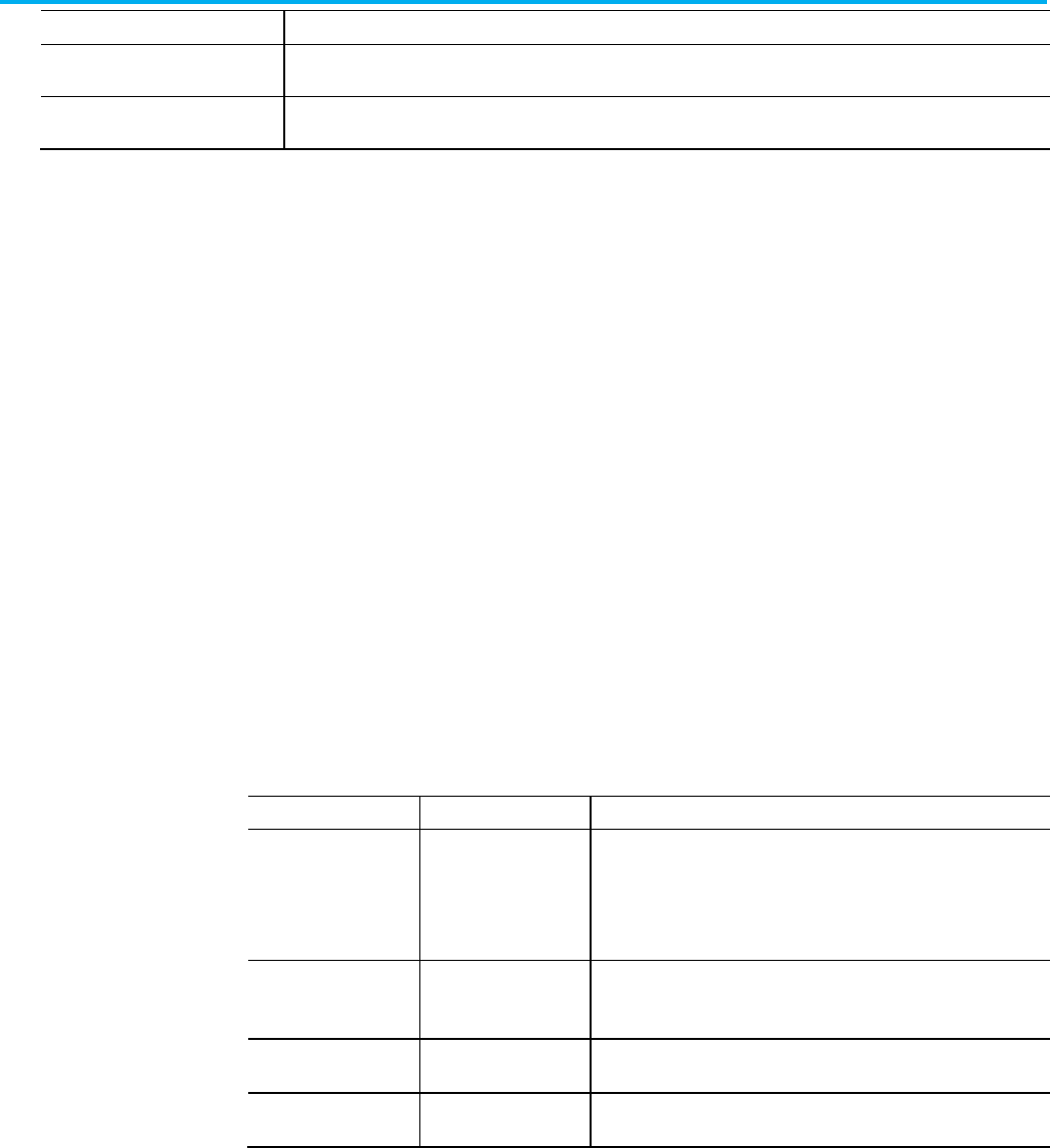
Chapter 6 Define a tag component
Publication 1756-RM014B-EN-P - November 2023 131
Attribute
Description
Alternate1UpdateMultiplier
Specify the value that is multiplied by the Base Update Period, which was previously called the Coarse Update Period. The
result is displayed as the
Alternate 1 Update Period
.
Alternate2UpdateMultiplier Specify the value that is multiplied by the
Base Update Period
, which was previously called the Coarse Update Period. The
result is displayed as the Alternate 2 Update Period.
The HMIBC tag consists of the:
• L5X HMIBC structure
• L5X HMIBC structure
• HMIBC attributes
In an .L5X file, HMIBC attributes are in the Data element.
<Tag Name="MyHMIBC" TagType="Base" DataType="HMIBC"
ExternalAccess="Read/Write">
<Data Format="HMIBC">
<HMIBCParameters EnableIn="false" ProgFB="false"
BitIndex="0" TerminalCount="0"/>
</Data>
</Tag>
Refer to the L5K HMIBC structure.
TAG
myHMIBC : HMIBC (EnableIn := "false",
ProgFB := "false");
END_TAG
Refer to the L5X and L5K HMIBC attributes and descriptions.
L5X Item
L5K Item
Description
EnableIn EnableIn Relay Ladder: Corresponds to the rung state. Does not affect processing.
Function Block: If cleared, the instruction does not execute and outputs
are not updated. If set, the instruction executes. Default is set.
Structured Text: No effect. The instruction always executes.
Value: true or false
ProgFB ProgFB Program Feedback. For use by the user program. Not used by the
instruction.
Value:
true
or
false
BitIndex
L5X Only: Export only, ignored on import
Value: 0 - 65535
TerminalCount
L5X Only: Export only, ignored on import
Value: 0 - 65535
The SAFETY tag consists of the:
• L5X safety structure
• L5K SAFETY structure
• Safety tag attributes
In an .L5X file, safety attributes are in the Data element.
<Data Foamt="Safety">
HMIBC tag
L5X HMIBC structure
L5K HMIBC structure
HMIBC attributes
SAFETY tag
L5X safety structure
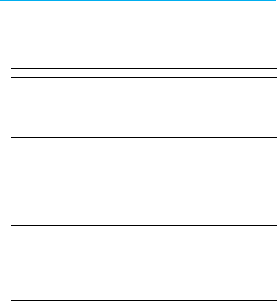
Chapter 6 Define a tag component
132 Publication 1756-RM014B-EN-P - November 2023
<SafetyParameters [Safety_Attributes]/>
</Data>
In an .L5K file, safety attributes are in the tag statement.
<tag_name> : <type>
[(Safety_Attributes)] := value;
A safety produced or safety consumed tag (Class = Safety) has these
attributes, and the attributes for a standard tag.
Attribute
Description
TimeoutMultiplier Specify the timeout multiplier (default = 2) for a safety controller system. This value determines the RPIs of
time to wait for a packet before declaring a time out. This translates into the number of messages that may be
lost before declaring a connection error. A Timeout Multiplier of 1 indicates that no messages may be lost,
which means there must be a packet every RPI interval. A Timeout Multiplier of 2 indicates that 1 message may
be lost, which means as long as a packet is seen in 2 times the RPI, no time-out will occur. Type a number
from 1...4, inclusive.
This attribute applies only to safety consumed tags.
For L5X, this attribute is on the <ConsumeInfo> element.
NetworkDelayMultiplier Specify the network delay multiplier (default = 100%) for a safety controller system. This value lets you reduce
or increase the connection reaction time limit in cases where the transport time of the message is
significantly less or more than the RPI. This may be the case when the RPI of an output connection is the same
as that of a lengthy task period. Type a percentage from 10...300, inclusive.
This attribute applies only to safety consumed tags.
For L5X, this attribute is on the <ConsumeInfo> element.
ReactionTimeLimit
Specify the connection reaction time limit for a safety controller system. The Logix Designer application
calculates the connection reaction time limit as a function of the RPI, timeout multiplier, and network delay
multiplier. The connection reaction time limit is automatically recalculated if any of the above values change.
This attribute applies only to safety consumed tags.
For L5X, this attribute is on the <ConsumeInfo> element.
MaxObservedNetworkDelay L5X only. MaxObservedNetworkDelay is a measure of the longest time the data of a safety connection is
delayed from transporting the safety packets over the network. This attribute is exported for informational
purposes only and is ignored on import.
This attribute is on the <ConsumeInfo> element.
Unicast For a safety consumed tag, specify if the EtherNet/IP connection is unicast. Specify
yes
for unicast or
no
to
remain multicast. For L5X format, specify
true
or
false
.
On export, only appears if the path to the producing module crosses an EtherNet/IP network and the producing
module supports unicast.
UnicastPermitted For a safety produced tag, specify whether let the EtherNet/IP connection be unicast. Specify
yes
for unicast
or no to remain multicast. For L5X format, specify true or false.
The Tag initial values section consists of:
• L5X initial tag value
• L5K initial TAG value
• Add-On Instruction tag values
• Add-On Instruction tag values example
• Tag guidelines
L5K SAFETY structure
Safety tag attributes
Tag initial values

Chapter 6 Define a tag component
Publication 1756-RM014B-EN-P - November 2023 133
• Examples
In an .L5X file, place the initial value of the tag in the Data element. See
Chapter 1 Data Formats on page 43 for more information on Data elements.
<Data>
initial_value
</Data>
If the tag is a string tag, specify a Format attribute.
<Data Format="String" Length="value">
<[CDATA[‘string text’]]>
</Data>
In L5X format, the string is padded with zeros (00) to fill its maximum of
82 characters.
In an .L5K file, place the initial value of the tag in the tag statement.
<tag_name> : <type> [(Attributes)][:= <initial_value>];
If the tag is a string tag, specify a STRING type.
<tag_name> : STRING := [<length>, ‘string_text$00 ... $00’];
The string is padded with zeros ($00) to fill its maximum of 82 characters.
The Logix Designer application optimizes user memory usage by minimizing
unused space in tags whose type is an Add-On Instruction data type.
The values for the Input & Output parameters are represented in the order as
they are listed in the Add-On Instruction definition. This rule applies to all
parameter data types except for BOOL. In order to reduce the data size of a
tag of Add-On Instruction type, BOOL parameters and BOOL local tags are
collected and packed in one or more hidden DINT members. Up to 32 BOOLs
are packed into each hidden DINT member. That is, the first BOOL is at bit 0,
the second BOOL is at bit 1. The hidden DINT members are located at the
position where the 1st, 33rd, 65th, (n*32+1) BOOL is located. See the example.
The values for the local tags are represented in the order listed in the Add-On
Instruction definition except as noted here. BOOL local tags are packed with
BOOL parameters. In order to reduce the data size of an Add-On Instruction
type tag, SINT and INT tags may be repositioned.
This is done because all types except SINT and INT must be aligned on a
four-byte boundary. When a SINT precedes a DINT, there are three unused
bytes between the two members. To optimize memory usage, the unused
space is filled with other SINTs and/or INTs when possible. Note that the free
L5X initial tag value
L5K initial TAG value
Add-On Instruction tag
values
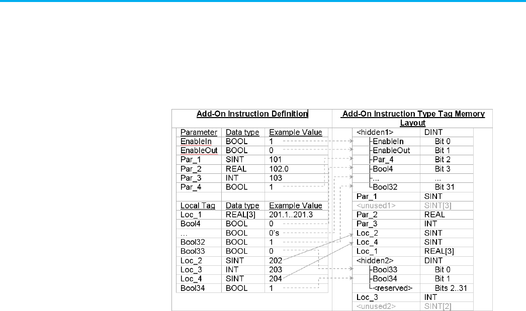
Chapter 6 Define a tag component
134 Publication 1756-RM014B-EN-P - November 2023
space optimization begins immediately after the last parameter. See the
example.
This example demonstrates the tag memory layout of an Add-On Instruction
definition. The dashed lines show where the BOOL members are located in
memory. The solid lines indicate where a local member is repositioned to
minimize unused space.
The L5K representation of an Add-On Instruction type tag containing the
example values is: [-2147483643, 101, 102.0, 103, 202, 204, [201.1, 201.2, 201.3], 2,
203].
• The <unused1> memory area aligns the member, Par_2, on a 4-byte
boundary. All types except for SINT and INT must be aligned on a
4-byte boundary. INTs must be aligned on a 2-byte boundary.
• The <unused2> memory area pads the Add-On Instruction type tag
such that the byte length is a multiple of 4.
• Unused data is not included in the L5K format. Unused data is
included in the L5X format.
• The simplest way to guarantee that the order of the parameters and
local tags in the L5K Add-On Instruction definition matches the order
of data values in the L5K Add-On Instruction type tag is to order the
tags in the LOCAL_TAGS section such that all SINTs are first, followed
by all INTs, and everything else.
Observe these guidelines when defining a tag.
• Tags must be defined after modules and add-on instructions. If there
are no modules or add-on instructions, then the tags must be defined
after the data types within the controller body.
• Base tags and aliases can be defined out of order within a tag block.
• You cannot define a second dimension without a first dimension or a
third dimension without a second dimension.
Add-On Instruction tag
values example
Tag guidelines
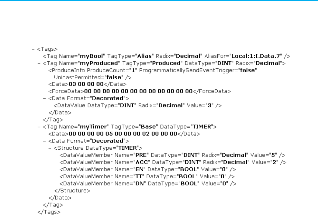
Chapter 6 Define a tag component
Publication 1756-RM014B-EN-P - November 2023 135
• The initial values must comply with the tag type and dimensions.
• Whitespace cannot occur within the initial values in L5K format or
within the type/dimension specifier.
L5X tag example
L5K TAG examples
TAG
bits : MySint := [0];
dest : INT (RADIX := Decimal) := 0;
overflow OF bits.MyBit0 (RADIX := Binary);
source : REAL (RADIX := Exponential) := 0.0;
timer : TIMER[3] := [[0,0,100],[0,10,100],[0,0,50]];
END_TAG
This example shows forced tag data.
TAG
dint_a : DINT (RADIX := Decimal) := 0;
int_a : INT (RADIX := Decimal) := 0;
tag_a : UDT_A (ProduceCount := 2) := [0,0],
TagForceData := [0,0,0,0,1,0,-1,-1,1,0,-72,34];
END_TAG
L5X safety tag example
Tag initial values examples
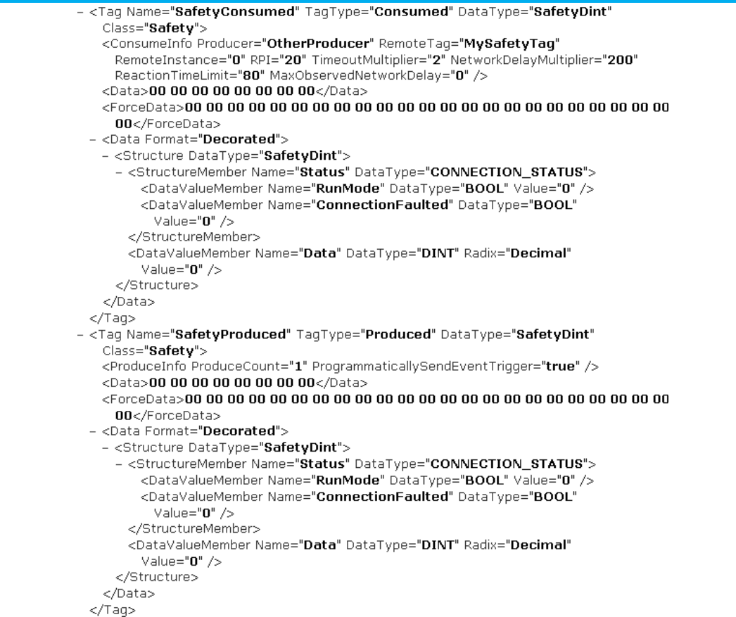
Chapter 6 Define a tag component
136 Publication 1756-RM014B-EN-P - November 2023
L5K safety TAG examples
This example shows a consumed tag in a safety project.
safetyConsumed : mypcType (Class := Safety,
Producer := PeerSafetyController,
RemoteTag := productCount,
RemoteFile := 0,
RPI := 10,
IncludeConnectionStatus := Yes,
TimeoutMultiplier := 2,
NetworkDelayMultiplier := 100,
ReactionTimeLimit := 29.952) := [[2],[0,0,0]],
TagForceData :=
[0,0,0,0,0,0,0,0,0,0,0,0,0,0,0,0,0,0,0,0,0,0,0,0,0,0,0,
0,0,0,0,0,0,0,0,0,0,0,0,0,0,0,0,0,0,0,0,0];
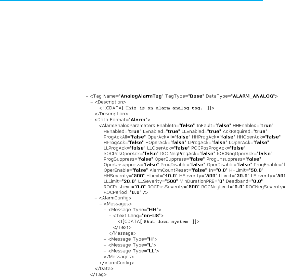
Chapter 6 Define a tag component
Publication 1756-RM014B-EN-P - November 2023 137
This example shows a produced tag in a safety project:
safetyProduced : mypcType (Class := Safety,
ProduceCount := 3,
ProgrammaticallySendEventTrigger := Yes,
IncludeConnectionStatus := Yes) := [[0],[0,0,0]],
TagForceData :=
[0,0,0,0,0,0,0,0,0,0,0,0,0,0,0,0,0,0,0,0,0,0,0,0,0,0,0,
0,0,0,0,0,0,0,0,0,0,0,0,0,0,0,0,0,0,0,0,0];
L5X ALARM_ANALOG and ALARM_DIGITAL tag examples
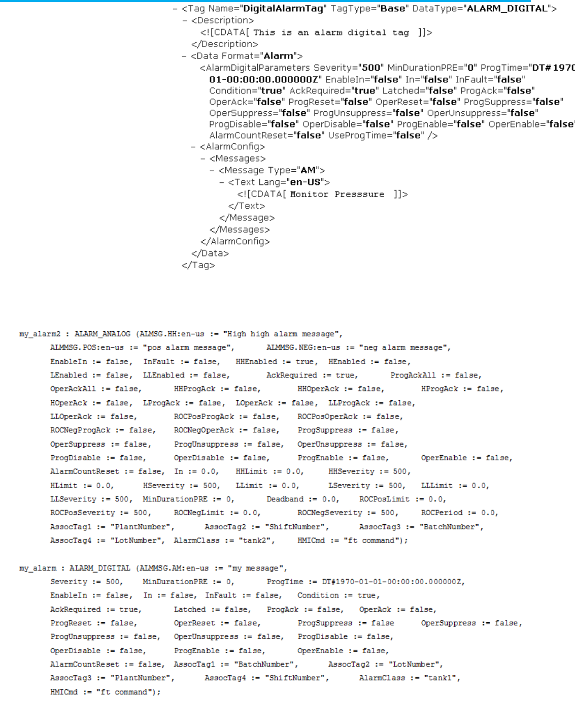
Chapter 6 Define a tag component
138 Publication 1756-RM014B-EN-P - November 2023
L5K ALARM_ANALOG and ALARM_DIGITAL tag examples

Chapter 6 Define a tag component
Publication 1756-RM014B-EN-P - November 2023 139

Publication 1756-RM014B-EN-P - November 2023 141
Chapter 7
Define a tag-based alarm or alarm definition
This chapter describes the structure of tag-based alarms and alarm
definitions.
A tag-based alarm is similar to a digital alarm in that it monitors a tag value to
determine the alarm condition. However, a tag-based alarm is not part of the
logic program and does not increase the scan time for a project. Use the New
Alarm dialog box to implement a tag-based alarm. An alarm definition is
associated with an Add-On Instruction (AOI) or a defined data type. When a
tag is created using a data type or an AOI that has alarm definitions, alarms
are created automatically based on the alarm definitions.
These sections describe the tag-based alarm structure, objects, and attributes.
<Tags>
<Tag Name=" pTag2" TagType="Base" Alarm="DINT"
Radix="Decimal" Constant="false" ExternalAccess="Read/Write">
<AlarmConditions>
<AlarmCondition Name="Tag2HHH" Input=".1"
ConditionType="HIHI" Limit="0.0" Severity="500" DelayOn="0"
DelayOff="0" ShelveDuration="0" MaxShelveDuration="0"
Deadband="0.0" Used="false" InFault="false" AckRequired="true"
Latched="false" ProgAck="false" OperAck="false" ProgReset="false"
OperReset="false" ProgSuppress="false" OperSuppress="false"
ProgUnsuppress="false" OperUnsuppress="false"
OperShelve="false" ProgUnshelve="false" OperUnshelve="false"
ProgDisable="false" OperDisable="false" ProgEnable="false"
OperEnable="false" AlarmCountReset="false"
GroupOperExcluded="false" GroupRollupExcluded="false"
EvaluationGroup="500 millisecond" Expression="Input = Limit"
AssocTag1="dint" AssocTag2="in" AssocTag3="TotalAlarmCount"
AssocTag4="TotalAlarmCount.1">
<AlarmConfig>
<Messages>
<Message Type="CAM">
Tag-based alarms
introduction
Tag-based alarms
L5X Tag-based alarm
structure

Chapter 7 Define a tag-based alarm or alarm definition
142 Publication 1756-RM014B-EN-P - November 2023
<Text Lang="en-US">
<![CDATA[Message]]>
</Text>
</Message>
</Messages>
<AlarmClass>
<![CDATA[Class]]>
</AlarmClass>
<HMIGroup>
<![CDATA[FT Group]]>
</HMIGroup>
<HMICmd>
<![CDATA[FT View command]]>
</HMICmd>
</AlarmConfig>
</AlarmCondition>
</AlarmConditions>
<Data Format="L5K">
<![CDATA[0]]>
</Data>
<Data Format="Decorated">
<DataValue DataType="DINT" Radix="Decimal" Value="0"/>
</Data>
</Tag>
</Tags>
Each alarm starts with ALARM_CONDITION and ends with
END_ALARM_CONDITION. The alarm definitions location in the L5K file will
be after the tasks. The example below is an alarm that was based on an alarm
definition.
ALARM_CONDITION PVHH (Name := "PVHH",
AlarmConditionDefinition := "PVHH",
L5K Tag-based alarm
structure

Chapter 7 Define a tag-based alarm or alarm definition
Publication 1756-RM014B-EN-P - November 2023 143
Input := "test.PVFault",
ConditionType := "TRIP",
Limit := 0.0,
Severity := 500,
OnDelay := 500,
OffDelay := 1000,
DefaultShelveDuration := 0,
MaxShelveDuration := 0,
Deadband := 0.0,
Used := true,
InFault := false,
AckRequired := true,
Latched := false,
ProgAck := false,
OperAck := false,
ProgReset := false,
OperReset := false,
ProgSuppress := false,
OperSuppress := false,
ProgUnsuppress := false,
OperUnsuppress := false,
OperShelve := false,
ProgUnshelve := false,
OperUnshelve := false,
ProgDisable := false,
OperDisable := false,
ProgEnable := false,
OperEnable := false,
AlarmCountReset := false,
AlarmSetOperIncluded := false,
AlarmSetRollupIncluded := false,
EvaluationPeriod := 2,

Chapter 7 Define a tag-based alarm or alarm definition
144 Publication 1756-RM014B-EN-P - November 2023
Expression := 19,
AssocTag1 := "test.EnableIn",
AssocTag2 := "test.SPHLimit",
AssocTag3 := "test.SPLLimit")
END_ALARM_CONDITION
The following example is for an alarm that is not based on an alarm definition
and has one localized message.
ALARM_CONDITION HH (ALMMSG.CAM:zh-TW := "mmm",
Name := "HH",
Input := "\MainProgram.bool",
ConditionType := "TRIP",
Limit := 0.0,
Severity := 500,
OnDelay := 0,
OffDelay := 0,
DefaultShelveDuration := 0,
MaxShelveDuration := 0,
Deadband := 0.0,
Used := true,
InFault := false,
AckRequired := true,
Latched := false,
ProgAck := false,
OperAck := false,
ProgReset := false,
OperReset := false,
ProgSuppress := false,
OperSuppress := false,
ProgUnsuppress := false,
OperUnsuppress := false,
OperShelve := false,

Chapter 7 Define a tag-based alarm or alarm definition
Publication 1756-RM014B-EN-P - November 2023 145
ProgUnshelve := false,
OperUnshelve := false,
ProgDisable := false,
OperDisable := false,
ProgEnable := false,
OperEnable := false,
AlarmCountReset := false,
AlarmSetOperIncluded := true,
AlarmSetRollupIncluded := true,
EvaluationPeriod := 2,
Expression := 128,
AlarmClass := "aaa",
HMICmd := "ccc")
END_ALARM_CONDITION
This section describes tag-based alarm objects and their attributes.
Alarm Conditions
Alarm conditions are a collection of the alarms for a tag.
• AlarmCondition -- An alarm condition in this collection for this tag.
Alarm Condition
The alarm condition on a tag. The following table lists Alarm Condition
attributes.
Programmatic Name
Attribute Description
Name
The name of the alarm.
Input Fully qualified path of a Scalar Tag Item that has this alarm.
Condition
The alarm condition type. See table below for values and the relation to the input data type.
AlarmConditionDefinition
The alarm condition definition that this alarm is based on.
Evaluation Period How frequently the alarm limit will be evaluated.
There is only one evaluation period and it is 500.
Expression The expression for evaluating the condition compared to the limit. See the table below for the expression for the
various condition types.
Limit Alarm limit.
Default = 0.0.
Tag-based alarm objects

Chapter 7 Define a tag-based alarm or alarm definition
146 Publication 1756-RM014B-EN-P - November 2023
Programmatic Name
Attribute Description
TargetTag Tag used to in the condition’s expression for input datatypes that are not BOOL or BIT.
AssocTag1
AssocTag2
AssocTag3
AssocTag4
Up to four specified tags that contain pertinent data when alarm conditions occur. A snapshot of the values in
these tags is stored whenever the status changes to the In Alarm state, or other alarm state changes occur. The
stored values may also be embedded in the alarm Message.
Severity Severity of the High alarm condition. This does not affect processing of alarms by the controller, but can be used
for sorting and filtering functions at the alarm subscriber.
Valid = 1...1000 (1000 = most severe; 1 = least severe).
Default = 500.
OnDelay Duration (milliseconds) for the alarm condition to remain true before the alarm is marked as InAlarm and alarm
notification is sent to clients. The controller collects alarm data as soon as the alarm condition is detected, so no
data is lost while waiting to meet the minimum duration.
Valid = 0...2147483647.
Default = 0.
OffDelay
Duration (milliseconds) for the alarm condition to remain false before the alarm is marked as not InAlarm and
alarm notification is sent to clients. The controller collects alarm data as soon as the alarm condition is detected,
so no data is lost while waiting to meet the minimum duration.
Valid = 0...2147483647.
Default = 0.
ShelveDuration
Time duration (in minutes) for which a shelved alarm will be shelved. Minimum time is one minute. Maximum time
is defined by MaxShelveDuration.
MaxShelveDuration
Maximum time duration (in minutes) for which an alarm can be shelved.
Deadband Deadband for detecting when the alarm levels have returned to normal.
A non-zero Deadband can reduce alarm condition chattering if the In value is continually changing but remaining
near the level condition threshold. The Deadband value does not affect the transition to the InAlarm (active) state.
Default = 0.0.
InFault Bad health indicator for the input. The user application may set InFault to indicate the input signal has an error.
When set, the instruction sets InFaulted (Status.1). When cleared, the instruction clears InFaulted (Status.1). In either
case, the instruction continues to evaluate In for alarm conditions.
Default is cleared (good health).
AckRequired Specifies whether alarm acknowledgment is required. When set, acknowledgment is required. When cleared,
acknowledgment is not required and Acked is always set.
Default is set.
Latched Specifies whether the alarm is latched. Latched alarms remain InAlarm when the alarm condition becomes false,
until a Reset command is received. When set, the alarm is latched. When cleared, the alarm is unlatched.
Default is cleared.
A latched alarm can only be reset when the alarm condition is false.
Default is cleared.
ProgAck Set by the user program to acknowledge the alarm. Takes effect only if the alarm is unacknowledged. Requires a
cleared-to-set transition.
OperAck Set by the operator interface to acknowledge the alarm. Takes effect only if the alarm is unacknowledged. The
instruction clears this parameter.
Default is cleared.
ProgReset Set by the user program to reset the latched alarm. Takes effect only if the latched alarm is InAlarm and the alarm
condition is false. Requires a cleared-to-set transition.
OperReset Set by the operator interface to reset the latched alarm. Takes effect only if the latched alarm is InAlarm and the
alarm condition is false. The alarm instruction clears this parameter.
Default is cleared.
ProgSuppress Set by the user program to suppress the alarm.
Default is cleared.
OperSuppress Set by the operator interface to suppress the alarm. The alarm instruction clears this parameter.
Default is cleared.
Chapter 7 Define a tag-based alarm or alarm definition
Publication 1756-RM014B-EN-P - November 2023 147
Programmatic Name
Attribute Description
ProgUnsuppress Set by the user program to unsuppress the alarm. Takes precedence over Suppress commands.
Default is cleared.
OperUnsuppress Set by the operator interface to suppress the alarm. The alarm instruction clears this parameter.
Default is cleared.
OperShelve Set by the operator interface to shelve or reshelve the alarm. Requires a transition from a cleared state in one
program scan to a set state in the next program scan. The alarm instruction clears this parameter. Default is
cleared.
Unshelve commands take precedence over Shelve commands.
Shelving an alarm postpones alarm processing. It is like suppressing an alarm, except that shelving is time-limited.
If an alarm is acknowledged while it is shelved, it remains acknowledged even if it becomes active again. It
becomes unacknowledged when the shelve duration ends provided the alarm is still active at that moment.
ProgUnshelve Set by the user program to unshelve the alarm. Takes precedence over Shelve commands. Default is cleared.
For more information on shelving an alarm, see the description for the OperShelve parameter.
OperUnshelve Set by the operator interface to unshelve the alarm. The alarm instruction clears this parameter. Takes precedence
over Shelve commands. Default is cleared.
For more information on shelving an alarm, see the description for the OperShelve parameter.
ProgDisable Set by the user program to disable the alarm.
Default is cleared.
OperDisable Set by the operator interface to disable the alarm. The alarm instruction clears this parameter.
Default is cleared.
ProgEnable
Set by the user program to enable the alarm. Takes precedence over a Disable command.
OperEnable Set by the operator interface to enable the alarm. Takes precedence over Disable command. The alarm instruction
clears this parameter.
Default is cleared.
AlarmCountReset Set by the operator interface to reset the alarm count to zero. The alarm instruction clears this parameter. Default
is cleared.
Used Indicates whether the alarm instance is used or not:
True (1) – Alarm instance is used
False (0) – Alarm instance is not used
AlarmSetOperIncluded
Boolean opting in or out of having any operation done on the alarm set is also done on this alarm.
AlarmSetRollupIncluded Boolean opting in or out of whether this alarm is included in the alarm sets’ count.
AlarmConfig Additional Configuration for this alarm. Includes the following four elements:
• AlarmMessages -- Messages that are displayed when the alarm is activated.
• AlarmClass -- String grouping together related alarms.
• HMICmd -- Command string that gets executed on the HMI when the alarm is activated.
•
HMIGroup -- String grouping together related alarm for the HMI.
The following table lists alarm condition types.
Input Data Type
Condition Type
Example Expression
BOOL/BIT
TRIP
Input=0
BOOL/BIT HIHI
HI
LO
LOLO
DEV_HI
DEV_LO
ROC_POS
ROC_NEG
Input=0
Numeric (DINT, REAL, etc.) HIHI
HI
Input>Limit

Chapter 7 Define a tag-based alarm or alarm definition
148 Publication 1756-RM014B-EN-P - November 2023
Input Data Type
Condition Type
Example Expression
Numeric (DINT, REAL, etc.) LO
LOLO
Input<Limit
Numeric (DINT, REAL, etc.)
LOLO
Input>Limit
Numeric (DINT, REAL, etc.)
ROC_POS
Input >= Limit
Numeric (DINT, REAL, etc.) ROC_NEG Input <= Limit
Numeric (DINT, REAL, etc.)
DEV_HI
Input >= TargetTag + Limit
Numeric (DINT, REAL, etc.)
DEV_LO
Input <= TargetTag - Limit
AlarmConfig
Provides the following additional attributes:
• AlarmMessages -- Messages that are displayed when the alarm is
activated.
• AlarmClass -- String grouping together related alarms.
• HMICmd -- Command string that gets executed on the HMI when the
alarm is activated.
• HMIGroup -- String grouping together related alarm for the HMI.
AlarmMessages
Contains the messages for the alarm.
AlarmMessage
A message for the alarm. Includes the following attributes:
• Type -- Must be CAM.
• Text -- The text of the alarm message.
Text
The text of the alarm message in a language. Includes the following attributes:
• Lang -- Language for the alarm message.
• Value -- Content of the alarm message.
This sections describe the tag-based alarm definition structure, objects, and
attributes.
Tag-based alarm
definitions

Chapter 7 Define a tag-based alarm or alarm definition
Publication 1756-RM014B-EN-P - November 2023 149
<AlarmDefinitions>
<DataTypeAlarmDefinition Name="PID_ENHANCED">
<MemberAlarmDefinition Name="HH" Input=".SP" ConditionType="HIHI"
Limit="0.0" Severity="500" DelayOn="0" DelayOff="0" ShelveDuration="0"
MaxShelveDuration="0" Deadband="0.0" Required="false" InFault="false"
AckRequired="true" Latched="false" GroupOperExcluded="false"
GroupRollupExcluded="false" EvaluationGroup="500 millisecond"
Expression="Input = Limit" AssocTag1=" .PV" AssocTag2=" .CV" >
<AlarmConfig>
<Messages>
<Message Type="ADM">
<Text Lang="en-US">
<![CDATA[Message]]>
</Text>
</Message>
</Messages>
<AlarmClass>
<![CDATA[Class]]>
</AlarmClass>
<HMIGroup>
<![CDATA[FT Group]]>
</HMIGroup>
<HMICmd>
<![CDATA[FT View command]]>
</HMICmd>
</AlarmConfig>
</MemberAlarmDefinition >
</DataTypeAlarmDefinition >
</AlarmDefinitions>
<Tags>
L5X Tag-based alarm
definition structure

Chapter 7 Define a tag-based alarm or alarm definition
150 Publication 1756-RM014B-EN-P - November 2023
ALARM_DEFINITION PVHH (ALMMSG.ADM:en-US := "PIDE Message 3",
ALMMSG.ADM:zh-TW := "This is my
message",
Name := "PVHH",
Input := "PID_ENHANCED.PVFault",
ConditionType := "TRIP",
Limit := 0.0,
Severity := 500,
OnDelay := 500,
OffDelay := 1000,
DefaultShelveDuration := 0,
MaxShelveDuration := 0,
Deadband := 0.0,
Required := true,
InFault := false,
AckRequired := true,
Latched := false,
AlarmSetOperIncluded := false,
AlarmSetRollupIncluded := false,
EvaluationPeriod := 2,
Expression := 19,
AssocTag1 := "PID_ENHANCED.EnableIn",
AssocTag2 :=
"PID_ENHANCED.SPHLimit",
AssocTag3 := "PID_ENHANCED.SPLLimit",
AlarmClass := "My Class",
HMICmd := "My FT View Command")
END_ALARM_DEFINITION
This section describes tag-based alarm definition objects and their attributes.
L5K Tag-based alarm
definition structure
Tag-based alarm definition
objects
Chapter 7 Define a tag-based alarm or alarm definition
Publication 1756-RM014B-EN-P - November 2023 151
AlarmDefinitions
The collection of all of the alarm definitions in the project.
• DatatypeAlarmDefinition -- The alarm definitions for a specific
datatype.
DataTypeAlarmDefinition
The collection of the alarm definitions for a specific datatype.
• Name -- The name of the datatype that these alarm definitions are for.
• MemberAlarmDefinition -- The alarm definitions for a specific
member of this datatype.
MemberAlarmDefinition
The alarm definition for a specific member of a datatype. The following table
describes the alarm definition attributes.
Programmatic Name
Attribute Description
Name
The name of the alarm definition.
Input
Fully qualified path of a datatype member that this alarm definition is on.
ConditionType The alarm condition type.
Evaluation Period How frequently the alarm limit will be evaluated.
There is only one evaluation period and it is 500.
Expression
The expression for evaluating the condition compared to the limit.
Limit Alarm limit.
Default = 0.0.
TargetTag
Tag used to in the condition’s expression for input datatypes that are not BOOL or BIT.
AssocTag1
AssocTag2
AssocTag3
AssocTag4
Up to four specified tags that contain pertinent data when alarm conditions occur. A snapshot of the values in these
tags is stored whenever the status changes to the In Alarm state, or other alarm state changes occur. The stored
values may also be embedded in the alarm Message.
Severity Severity of the High alarm condition. This does not affect processing of alarms by the controller, but can be used for
sorting and filtering functions at the alarm subscriber.
Valid = 1...1000 (1000 = most severe; 1 = least severe).
Default = 500.
OnDelay Duration (milliseconds) for the alarm condition to remain true before the alarm is marked as InAlarm and alarm
notification is sent to clients. The controller collects alarm data as soon as the alarm condition is detected; so no
data is lost while waiting to meet the minimum duration.
Valid = 0...2147483647.
Default = 0.
OffDelay Duration (milliseconds) for the alarm condition to remain false before the alarm is marked as not InAlarm and alarm
notification is sent to clients. The controller collects alarm data as soon as the alarm condition is detected; so no
data is lost while waiting to meet the minimum duration.
Valid = 0...2147483647.
Default = 0.
ShelveDuration Time duration (in minutes) for which a shelved alarm will be shelved. Minimum time is one minute. Maximum time is
defined by MaxShelveDuration.
Chapter 7 Define a tag-based alarm or alarm definition
152 Publication 1756-RM014B-EN-P - November 2023
Programmatic Name
Attribute Description
MaxShelveDuration Maximum time duration (in minutes) for which an alarm can be shelved.
Deadband Deadband for detecting when the alarm levels have returned to normal.
A non-zero Deadband can reduce alarm condition chattering if the In value is continually changing but remaining
near the level condition threshold. The Deadband value does not affect the transition to the InAlarm (active) state.
Default = 0.0.
AckRequired Specifies whether alarm acknowledgment is required. When set, acknowledgment is required. When cleared,
acknowledgment is not required and Acked is always set.
Default is set.
Latched Specifies whether the alarm is latched. Latched alarms remain InAlarm when the alarm condition becomes false,
until a Reset command is received. When set, the alarm is latched. When cleared, the alarm is unlatched.
Default is cleared.
A latched alarm can only be reset when the alarm condition is false.
Default is cleared.
Required
Whether or not instances of this must always be marked as used
AlarmSetOperIncluded Boolean opting in or out of having any operation done on the alarm set is also done on this alarm.
AlarmSetRollupIncluded
Boolean opting in or out of whether this alarm is included in the alarm sets’ count.
AlarmConfig Additional Configuration for this alarm. Includes the following elements:
• AlarmMessages -- Messages that are displayed when the alarm is activated.
• AlarmClass -- String grouping together related alarms.
• HMICmd -- Command string that gets executed on the HMI when the alarm is activated.
•
HMIGroup -- String grouping together related alarm for the HMI.
Messages
The messages for this alarm definition.
Publication 1756-RM014B-EN-P - November 2023 153
Chapter 8
Define a program component
This chapter explains the overall structure of the Program component.
The Program component defines the programs used in the logic you export.
The maximum number of programs depends on the type of controller.
Controller
Maximum Number of Programs
ControlLogix 1000
(32 in firmware revisions prior to 15)
SoftLogix 5800 100
(32 in firmware revisions prior to 15)
FlexLogix 32
CompactLogix
32
DriveLogix 32
<Programs>
<Program [Program_Attributes]>
<Description>
<![CDATA[ text ]] >
</Description>
<Tags>
tags
</Tags>
<Routines>
routines
</Routines>
<ChildPrograms>
child_programs
</ChildPrograms>
</Program>
</Programs>
PROGRAM <program_name> [(Description := "text",
Program_Attributes)]
Program component
introduction
Program component
L5X program structure
Chapter 8 Define a program component
154 Publication 1756-RM014B-EN-P - November 2023
[TAG declaration]
[ROUTINE declaration]
[FBD_ROUTINE declaration]
[SFC_ROUTINE declaration]
[ST_ROUTINE declaration]
[CHILD_PROGRAMS]
END_PROGRAM
Refer to the L5X and L5K program elements and descriptions.
L5X Item
L5K Item
Description
Not applicable
program_name
The name of the program.
In L5X, use a Name attribute on the <Program> element.
Description Description User information about the program.
tags
TAG Program-scoped tags.
Follows same format as controller-scoped tags.
For more details on defining a tag, see Chapter 6 Defining a Tag Component on page
105.
routines
ROUTINE
FBD_ROUTINE
ST_ROUTINE
SFC_ROUTINE
Routines within the program.
For more details on defining a:
• Ladder logic routine, see Chapter 8 Defining a Ladder Logic Routine on page 163.
• Function block diagram routine, see Chapter 9 defining a Function Block Diagram
Routine on page 175.
• Sequential function chart routine, see Chapter 10 Defining a Sequential Function
Chart Routine on page 199.
• Structured text routine, see Chapter 11 Defining a Structured Text Routine on page
221.
ChildPrograms
CHILD_PROGRAMS Child programs of the parent program. The child-parent relationship is visible in only
the Logical Organizer in the Logix Designer application, and not in the Controller
Organizer.
Refer to the program attributes and descriptions.
Attribute
Description
Name L5X only. Specify the name of the program.
In L5K, the name is an element of the statement.
Type Specify the type of program. If this program is a Equipment Phase program, type
EquipmentPhase
. If this
program is a Sequence program, type Sequence. Otherwise, type Normal.
Class Specify the class of the program. This attribute applies only to safety controller projects. Type
Standard
or
Safety
. Do not use this attribute if the program is an Equipment Phase program.
(Type = EquipmentPhase).
Main (L5K)
MainRoutineName (L5X)
Specify the name of the main routine of the program (40 characters maximum).
Program elements
Program attributes

Chapter 8 Define a program component
Publication 1756-RM014B-EN-P - November 2023 155
Attribute
Description
Fault (L5K)
FaultRoutineName (L5X)
L5K only. Specify the name of the program fault routine, if any (40 characters maximum).
Mode
L5K only. Type 0 for not testing edits; type 1 for testing edits.
TestEdits
L5X only. Type false for not testing edits; type true for testing edits.
DisableFlag
L5K only. Type 1 to disable the program; type 0 to enable the program.
Disabled
L5X only. Type true to disable the program; type false to enable the program.
SynchronizeRedundancyData
AfterExecution
Type
1
to synchronize data after the program scan in a redundant system; type
0
to not synchronize data after
the program scan.
UseAsFolder Type
1
to use the program as a folder. Logix Designer application does not execute any routines or update any
parameters in a program that is used as a folder.
In addition to the program connection attributes previously described, an
Equipment Phase program (Program Type = EquipmentPhase) has the
following attributes.
Attribute
Description
PreState (L5K)
PreStateRoutineName (L5X)
L5K only. Specify the name of the prestate routine (40 characters maximum).
InitialStepIndex Specify an integer value for the initial step index of the phase.
InitialState
Specify state of the phase. Type Aborted, Completed, Stopped, or Idle (default).
CompleteStateIfNotImpl If the phase does not implement all the expected states, enter StateComplete (default) so the
program can continue to execute when it expects a state that was omitted. The program
ignores the omitted state and continues to the next state. Otherwise, enter NoAction.
LossOfCommCmd If the phase uses an external sequencer, such as FactoryTalk Batch
®
software, specify that
appropriate action to take if communication fails between the controller and the external
sequencer. Type Abort, Hold, Stop, or none (default).
ExternalRequestAction Specify how to handle an external request (PXRQ instruction) that is in process when the phase
receives the command to go to a Holding state. Type
Clear
to abort outstanding external
requests. Otherwise, type none (default).
EquipmentId The FactoryTalk Batch equipment identifier for the Equipment Phase. This value is set by the
FactoryTalk Batch software when you synchronize with a project file. Do not modify this value.
RecipePhaseNames The FactoryTalk Batch recipe phases for the Equipment Phase. This value is set by the
FactoryTalk Batch software when you synchronize with a project file. Do not modify this value.
AutoValueAssignStepToPhase Specify whether the value of sequence step inputs are automatically assigned to phase inputs
when a sequence step starts the phase and the phase is used in a sequence.
In L5K, type
Yes
or
No
. In L5X, type
true
or
false
.
AutoValueAssignPhaseToStepOnComplete Specify whether the value of phase outputs are automatically assigned to step outputs when
the phase is completed and the phase is used in a sequence.
In L5K, type Yes or No. In L5X, type true or false.
AutoValueAssignPhaseToStepOnStopped Specify whether the value of phase outputs are automatically assigned to step outputs when
the phase is stopped and the phase is used in a sequence.
In L5K, type
Yes
or
No
. In L5X, type
true
or
false
.
AutoValueAssignPhaseToStepOnAborted Specify whether the value of phase outputs are automatically assigned to step outputs when
the phase is stopped and the phase is used in a sequence.
In L5K, type
Yes
or
No
. In L5X, type
true
or
false
.
Program attributes for
EquipmentPhase programs
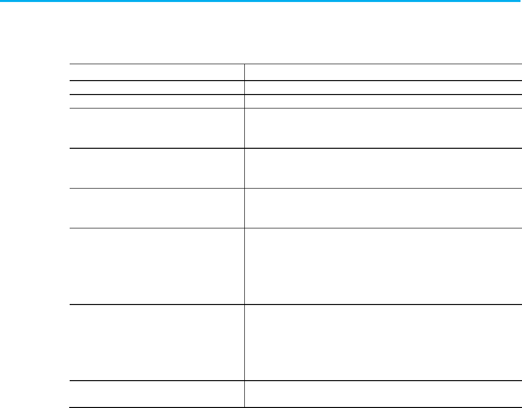
Chapter 8 Define a program component
156 Publication 1756-RM014B-EN-P - November 2023
In addition to the program connection attributes previously described, a
Sequence program (Program Type = Sequence) has the following attributes.
Attribute
Description
Revision Revision number for the program, consisting of major and minor revision.
RevisionExtension
Additional revision information.
UnitID Numeric identifier to designate the equipment that the sequence is controlling.
Example value: 1-0x7FFFFFFF
RetainSequenceIDOnReset Specify whether the sequence ID is retained when the sequence resets.
In L5K, type Yes or No. In L5X, type true or false.
GenerateSequenceEvents
Specify whether the sequence events are generated.
In L5K, type Yes or No. In L5X, type true or false.
ValuesToUseOnStart Specify the values of sequence parameters and step tags that are used when starting the
sequence.
•
Use Initial Values
– Copy the initial values to the current values when starting the
sequence.
•
Retain Current Values
– Use the current values of sequence parameters and step tags
when starting the sequence.
ValuesToUseOnReset Specify the how the values of sequence parameters and step tags are set when the
sequence resets.
•
Use Initial Values
– Restore the current values of sequence parameters and step tags to
the initial values when resetting the sequence.
•
Retain Current Values
– Maintain the current values of sequence parameters and step
tags when resetting the sequence.
RevisionNote Optional detailed information about the revision.
For L5X, this is a sub element: <RevisionNote>.
The Child Program component defines the child programs used in the logic
you export. A child program is a program defined as the logical child of
another program in the Logical Organizer in the Logix Designer.
Refer to the L5K CHILD_PROGRAM structure.
PROGRAM <program_name> [(Description := "text",
Program_Attributes)]
[TAG declaration]
[ROUTINE declaration]
[FBD_ROUTINE declaration]
[SFC_ROUTINE declaration]
[ST_ROUTINE declaration]
[CHILD_PROGRAMS]
END_PROGRAM
Program attributes for
Sequence programs
Child program component
L5K CHILD_PROGRAM
structure
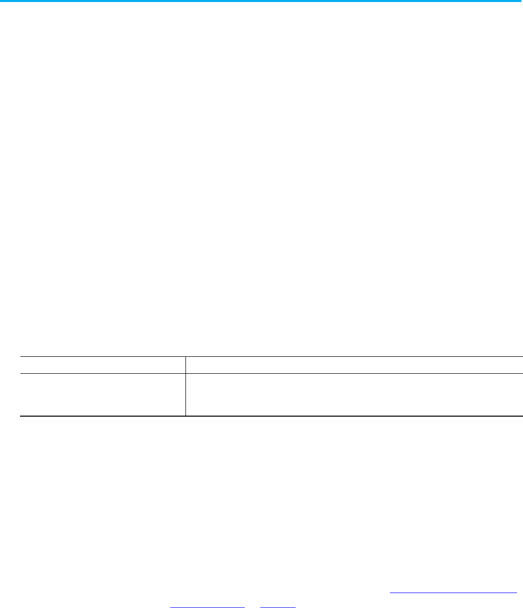
Chapter 8 Define a program component
Publication 1756-RM014B-EN-P - November 2023 157
Refer to the L5X child program structure.
<Programs>
<Program [Program_Attributes]>
<Description>
<![CDATA[ text ]] >
</Description>
<Tags>
tags
</Tags>
<Routines>
routines
</Routines>
<ChildPrograms>
child_programs
</ChildPrograms>
</Program>
</Programs>
See the table for the child program attribute and description.
Attribute
Description
child_program_name L5X only. Specify the name of the child program.
In L5K, the name is an element of the statement.
Observe these guidelines when defining a child program.
• Since child programs are a way to organize existing programs, adding
a child program component does not add to the number of programs.
These examples are for protected (encoded) and unprotected (clear text)
codes for routines.
If the project contains a source-protected routine, the routine appears within
an encoded data component in the program. See Exporting Source-protected
Logic on page 28 on page 35 for procedures.
Refer to the L5X EncodedData routines structure.
L5X child program structure
Child program attributes
Child program guidelines
Encoded/Unencoded
routines
L5X EncodedData Structure
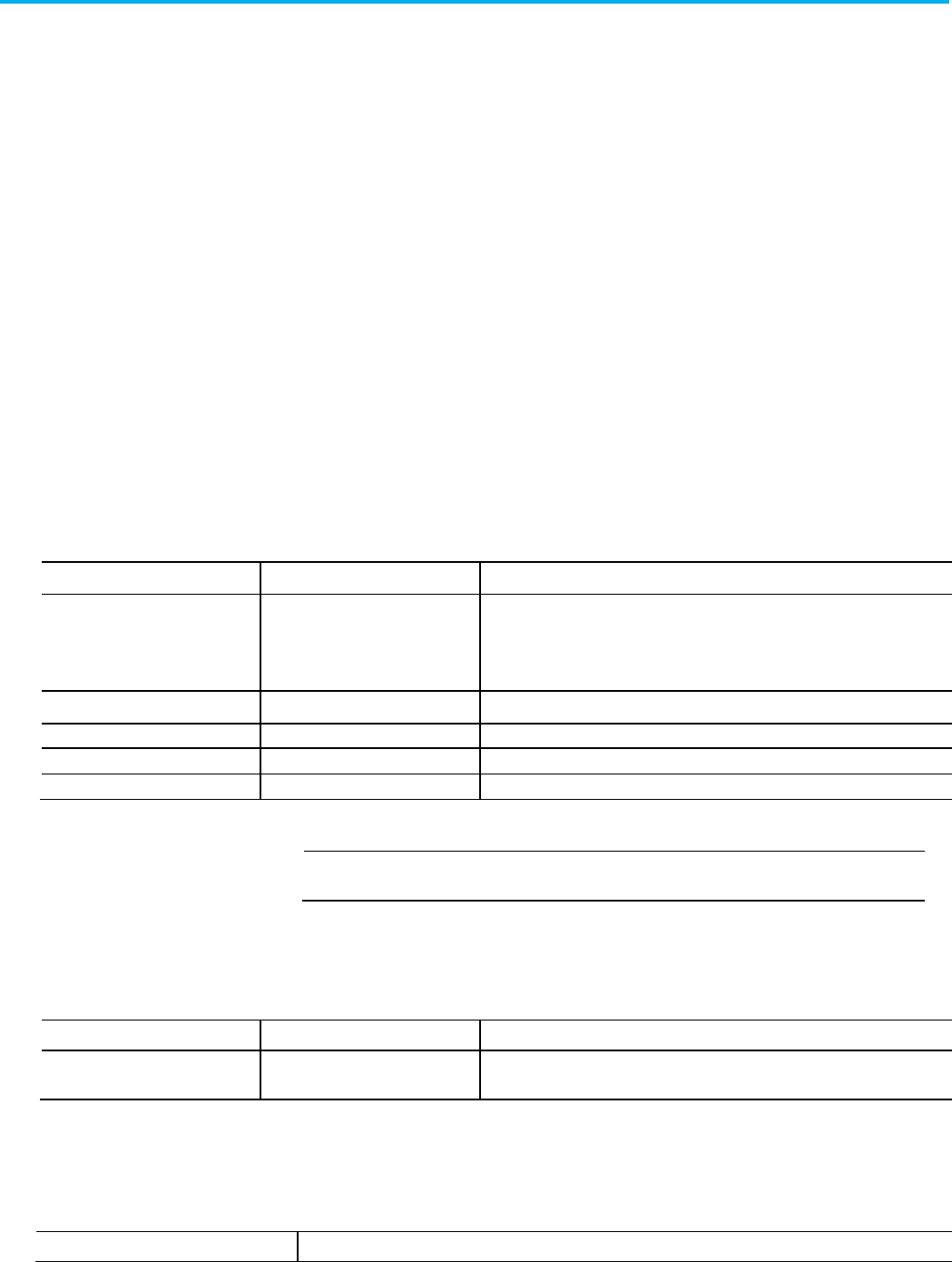
Chapter 8 Define a program component
158 Publication 1756-RM014B-EN-P - November 2023
<EncodedData EncodedType= "type", Name="name",
Type="routinetype"
[,other_attributes]>
<Description>
<![CDATA[ text ]] >
</Description>
encoded_data
</EncodedData>
Refer to the L5K ENCODED_DATA routines structure.
ENCODED_DATA [( EncodedType: type, Name:= name,
Type:= routinetype,
other_attributes)]
encoded_data
END_ENCODED_DATA
See the table for routine encoded data attributes for .L5X and .L5K items and
their descriptions.
L5X Item
L5K Item
Description
type
type
The type of data encoded.
For L5K: ROUTINE
For L5X: Routine
name
name
The name of the protected routine.
routinetype
routinetype
The type of the routine protected (RLL, FBD, SFC, or ST).
other_attributes
other_attributes
Attributes of the routine that are not protected during export.
encoded_data
encoded_data
The protected portion of the routine.
IMPORTANT
When the routine is source protected, the
encoded_data
information is encrypted. If
you modify this encrypted information, you will not be able to re-import the routine.
See the table for the encoded information element for the .L5X and .L5K item
and identifier.
L5X Item
L5K Item
Identifies
EncryptionKey ENCRYPTION_KEY Identifies the options the user has chosen for protecting and locking their content.
See the table for encoded key attributes and their descriptions.
Attribute
Description
L5K ENCODED_DATA
Structure
Encoded Data Elements
Encoded Information
elements
Encoded key attributes
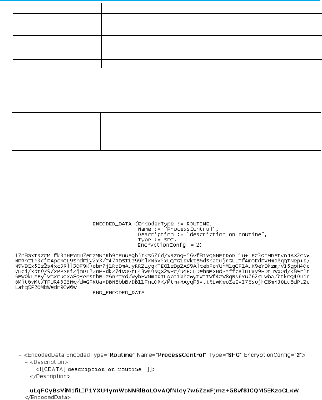
Chapter 8 Define a program component
Publication 1756-RM014B-EN-P - November 2023 159
Attribute
Description
Name
Identifies the type of protection.
ID Identifier for the key (Firm code, product code).
Description Description of what the key is associated with (license name).
Vendor Indicates the vendor who supplied the key.
PublicKey Stores the public key that will be used for the locking of the associated object.
This table contains encoded content attributes and their descriptions.
Attribute
Description
EncryptedType Indicates the underlying language of the routine for this encoded content (for example, RLL or Structured text).
OnlineEditType L5X only. Specify the online edit logic type (
Original
,
PendingEdits
, or
TestEdits
). This attribute is not specified if
there are no edits.
Refer to the L5K source protected routine example.
Refer to the L5X source-protected routine example.
Observe these guidelines when defining a program.
• Define the main and fault attributes in any order.
Encoded content attributes
L5K source protected
routine example
L5X source-protected
routine example
Program guidelines
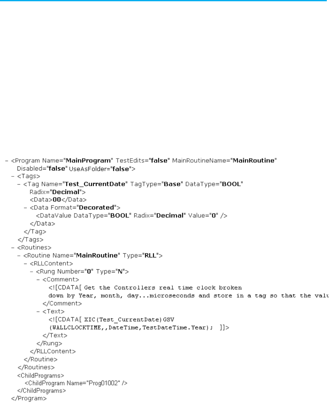
Chapter 8 Define a program component
160 Publication 1756-RM014B-EN-P - November 2023
• You must put the tag declaration block before the routine block.
• Define up to 1000 programs per task.
• When you import a project:
• All tag collection declaration blocks in a program definition block
are imported as local tags of a given program and are seen only by
routines under that program.
• Program parameters are imported as parameters of a given
program, but are seen by other tags, parameters, and routines in the
project.
• Controller tags are seen by routines in any program.
L5X Program Example
L5K PROGRAM Example
Program guidelines
examples
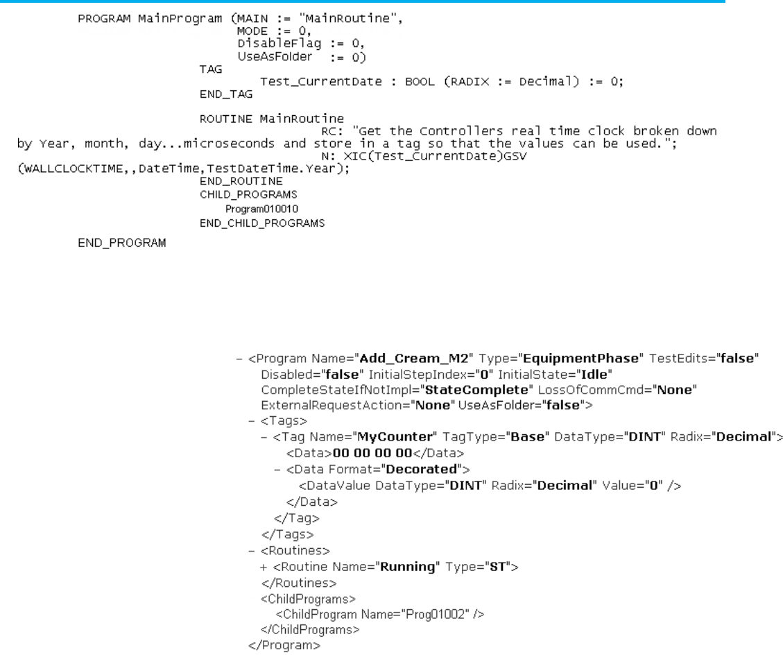
Chapter 8 Define a program component
Publication 1756-RM014B-EN-P - November 2023 161
L5X Equipment Phase Program Example
L5K Equipment Phase PROGRAM Example
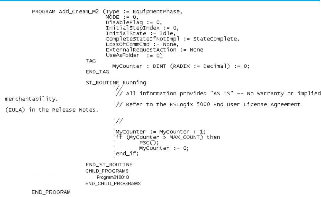
Chapter 8 Define a program component
162 Publication 1756-RM014B-EN-P - November 2023

Publication 1756-RM014B-EN-P - November 2023 163
Chapter 9
Define a ladder logic routine
This chapter explains how to enter ladder diagram logic in a complete
import/export file.
These examples show the ladder logic routine structure.
Refer to the L5K ladder logic routine structure.
<Routines>
<Routine [Routine_Attributes]>
<Description>
<![CDATA[ text ]] >
</Description>
<RLLContent>
logic
</RLLContent>
</Routine>
</Routines>
Refer to the L5K Ladder Logic ROUTINE structure.
ROUTINE <routine_name> [(Description := "text")]
<ladder_rungs>
END_ROUTINE
Refer to the L5X and L5K ladder logic routine elements and descriptions.
L5X Item
L5K Item
Description
N/A
routine_name
The name of the routine.
In L5X, use a Name attribute in the <Routine> element.
Description Description User information about the routine.
RLLContent
ladder_rungs
Rung logic.
EncryptionInfo ENCRYPTION_INFO Details of the license-based Source Protection for the lockable object. Only exists for
protected routines exported in plain text.
Ladder logic routine
introduction
Ladder logic routine
L5X ladder logic routine
structure
L5K Ladder Logic ROUTINE
structure
Ladder logic routine
elements
Chapter 9 Define a ladder logic routine
164 Publication 1756-RM014B-EN-P - November 2023
L5X Item
L5K Item
Description
EncryptedContent
N/A
Source Protected and locked routine content. Only exists for locked routines
exported in plain text.
EncryptedSegments
N/A
Locked logic for the routine. Only exists for locked routines exported in plain text.
Refer to the RLL routine attributes and descriptions.
Attribute
Description
Name L5X only. Specify the name of the routine.
In L5K, the name is an element of the statement.
Type L5X only. Specify RLL.
In L5K, the type of routine is part of the routine statement.
PermissionSet
Name of the set of permissions, configured in FactoryTalk Security, to apply to this object.
TrackingGroups The group of tracked objects to which this item belongs. Components can be marked for tracking to determine
whether they have been changed. Version 30 of the Logix Designer application supports only one tracking
group.
Enter rung logic within a routine component in an import/export file.
Refer to the L5X rung structure.
<RLLContent>
<Rung [Rung_Attributes]>
<Comment>
<![CDATA[ comment_text ]] >
</Comment>
<Text >
<![CDATA[ rung_neutral_text; ] ] >
</Text>
</Rung>
</RLLContent>
Refer to the L5K RUNG structure.
RC: "comment" "more" "etc";
<RungType> : <rung_neutral_text>;
RLL Routine attributes
Rung logic
L5X rung structure
L5K RUNG structure
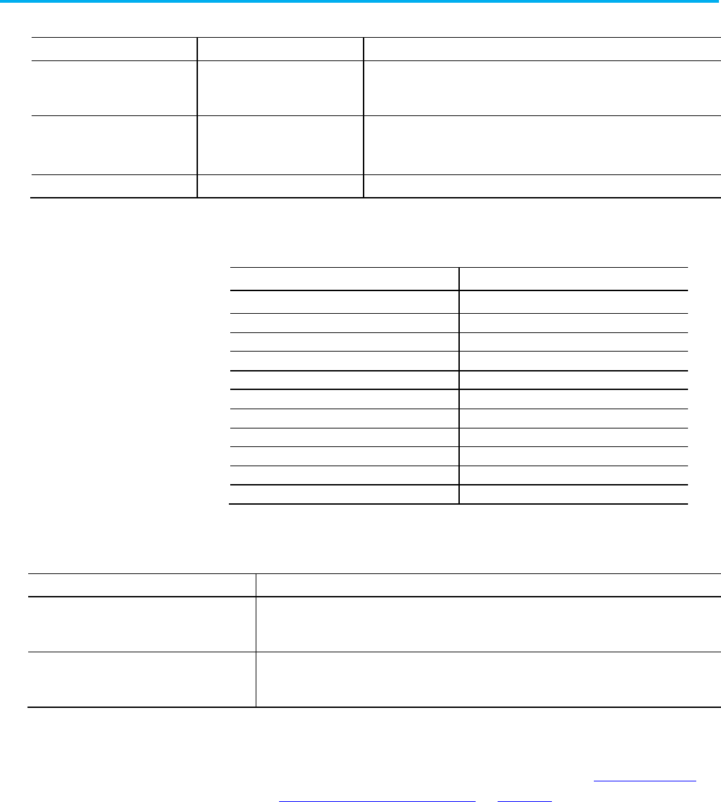
Chapter 9 Define a ladder logic routine
Publication 1756-RM014B-EN-P - November 2023 165
Refer to the L5X and L5K rung elements and descriptions.
L5X Item
L5K Item
Description
N/A
RungType
The type of rung.
In L5X, use a Type attribute on the <Rung> element.
Comment RC Rung comment.
In a L5K file, a rung comment must be followed by a rung.
Text
rung_neutral_text
The logic.
These rung types are available.
Item
Identifies
N Normal
I Insert
D
Delete
IR Insert with a replace
rR
Pending replace IR
R
Replace
rI
Pending replace I
rN
Pending replace N
e
Pending insert rung
er Pending replace rung
d Pending delete rung
Refer to the rung attributes and descriptions.
Attribute
Description
Number L5X only. Specify the rung number within the routine.
In L5K, the rung number is defined by the order the rung appears in the L5K format.
Type L5X only. Specify RLL.
In L5K, the type of rung is part of the rung statement.
Use these guidelines for rung logic:
• Rungs are specified by using neutral language. See Neutral Text for
Ladder Instructions on page 156 on page 167 for the format for the
supported instructions.
• Each rung ends with a semicolon (;)
Enter a single branch or simultaneous branches on a rung.
Rung elements
Rung attributes
Rung guidelines
Single or simultaneous
branches
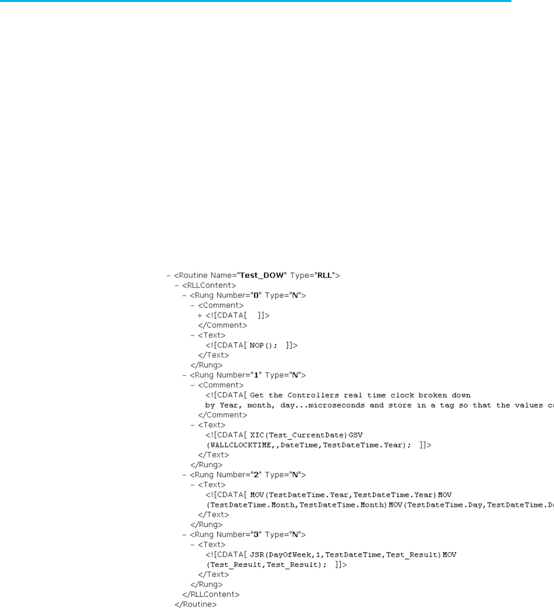
Chapter 9 Define a ladder logic routine
166 Publication 1756-RM014B-EN-P - November 2023
Refer to the L5X branch structure.
<Branch [BranchAttributes]>
<Leg [LegAttributes]/>
</Branch>
Refer to the L5K BRANCH structure.
BRANCH (Branch_Attributes)
LEG (Leg_Attributes)
END_LEG
END_BRANCH
L5X Ladder ROUTINE Example
L5X branch structure
L5K BRANCH structure
L5X Examples
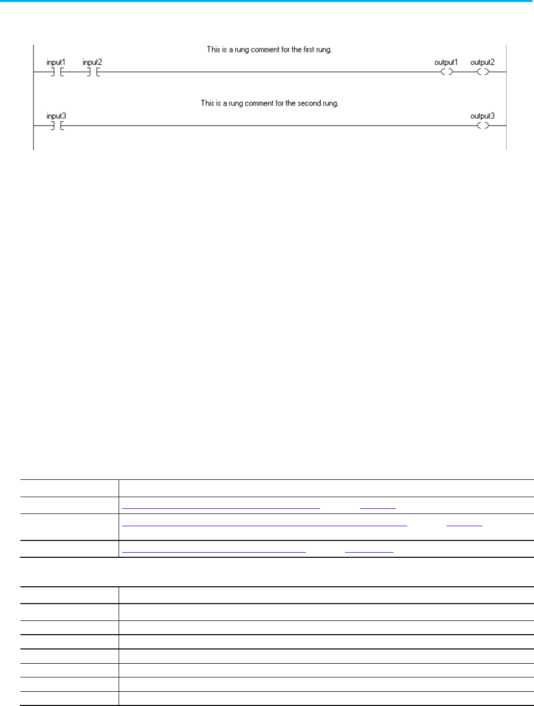
Chapter 9 Define a ladder logic routine
Publication 1756-RM014B-EN-P - November 2023 167
Ladder ROUTINE example
ROUTINE Ladder_example
RC: "This is a rung comment for the first rung.";
N: XIC(input1)XIC(input2)OTE(output1)OTE(output2);
RC: "This is a rung comment for the second rung.";
N: XIC(input3)OTE(output3);
END_ROUTINE
Example with a single branch
N: XIC(conveyor_a)[,XIC(input_1) XIO(input_2)
]OTE(light_1);
Example with two simultaneous branches
N: XIC(conveyor_b)[,XIC(input_1) XIO(input_2)
,XIC(input_a) XIO(input_b) ]OTE(light_2);
These tables lists each ladder instruction and its neutral text format. For
details about a specific instruction, see the listed reference manuals.
Ladder Logic Instruction Reference Manuals
Instruction Type
Resource
Basic, sequential instruction Logix5000 Controllers General Instructions Set Reference Manual, publication 1756-RM003
.
Process control or drives
instruction
Logix5000 Controllers Advanced Process Control and Drives Instruction Set Reference Manual, publication 1756-RM006
.
Motion instruction Logix5000 Controllers Motion Instructions Reference Manual, publication MOTION-RM002.
Relay Ladder Instructions
Instruction
Neutral Text Format
ABL ABL(
channel,serial_port_control,character_count
);
ABS ABS(
source,destination
);
ACB ACB(
channel,serial_port_control,character_count
);
ACL ACL(
channel,clear_serial_port_read,clear_serial_port_write
);
ACS
ACS(
source,destination
);
ADD
ADD(
source_A,source_B,destination
);
AFI
AFI();
L5K examples
Neutral text for ladder
instructions

Chapter 9 Define a ladder logic routine
168 Publication 1756-RM014B-EN-P - November 2023
Instruction
Neutral Text Format
AHL
AHL(
channel,ANDMask,ORMask,serial_port_control,channel_status
);
ALMA ALMA (
alma_tag
,
in
,
program_acknowledge_all
,
program_disable
,
program_enable
);
ALMD ALMD (
almd_tag,program_acknowledge,program_reset
,
program_disable
,
program_enable
);
AND AND(
source_A,source_B,destination
);
ARD ARD(
channel,destination,serial_port_control,string_length,
characters_read
);
ARL ARL(
channel,destination,serial_port_control,string_length,
characters_read
);
ASN ASN(
source,destination
);
ATN
ATN(
source,destination
);
AVC AVC(
avc_tag,feedback_type,feedback_reation_time,delay_type,delay_time,
output_follows_actuate,actuate,delay_enable,feedback_1,input_status,
output_status,reset
);
AVE AVE(
array,dim_to_vary,destination,control,length,position
);
AWA
AWA(
channel,source,serial_port_control,string_length,characters_sent
);
AWT
AWT(
channel,source,serial_port_control,string_length,characters_sent
);
BRK BRK();
BSL
BSL(
array,control,source_bit,length
);
BSR
BSR(
array,control,source_bit,length
);
BTD
BTD(
source,source_bit,destination,destination_bit,length
);
CBCM CBCM(
cbcm_tag,ack_type,mode,takeover_mode,enable,safety_enable,
standard_enable,arm_continuous,start,stop_at_top,press_in_motion,
motion_monitor_fault,slide_zone,safety_enable_ack
)
CBIM CBIM(
cbim_tag,ack_type,inch_time,enable,safety_enable,standard_enable,
start,press_in_motion,motion_monitor_fault,slide_zone,safety_enable_ack
);
CBSSM CBSSM(
cbssm_tag,ack_type,takeover_mode,enable,safety_enable,
standard_enable,start,press_in_motion,motion_monitor_fault,slide_zone,
saefty_enable_ack
);
CLR CLR(
destination
);
CMP
CMP(
expression
);
CONCAT
CONCAT(
sourceA,sourceB,destination
)
COP
COP(
source,destination,length
);
COS
COS(
source,destination
);
CPM CPM(
cpm_tag,cam_profile,enable,brake_cam,takeover_cam,dynamic_cam,
input_status,reverse,press_motion_status,reset
);
CPS CPS(
source,destination,length
);
CPT
CPT(
destination
,
expression
);
CROUT CROUT(
crout_tag,feedback_type,feedback_reaction_time,actuate,feedback_1,
feedback_2,input_status,output_status,reset
);
CSM
CSM(
csm_tag,mechanical_delay_timer,max_pulse_period,motion_request,
channel_A,channel_B,input_status,reset
);
CTD
CTD(
counter,preset,accum
);
CTU
CTU(
counter,preset,accum
);
DCM DCM(
dcm_tag,safety_function,input_type,descrepancy_time,channel_A,
channel_B,input_status,reset
);
DCS DCS(
dcs_tag,safety_function,input_type,discrepancy_time,restart_type,
cold_start_type,channel_A,channel_B,input_status,reset
);

Chapter 9 Define a ladder logic routine
Publication 1756-RM014B-EN-P - November 2023 169
Instruction
Neutral Text Format
DCSRT
DCSRT(
dcsrt_tag,safety_function,input_type,discrepancy_time,enable,
channel_A,channel_B,input_status,reset
);
DCST
DCST(
dcst_tag,safety_function,input_type,discrepancy_time,restart_type,
cold_start_type,channel_A,channel_B,test_request,input_status,reset
);
DCSTM DCSTM(
dcstm_tag,safety_function,input_type,discrepancy_time,restart_type,
cold_start_type,test_type,test_time,channel_A,channel_B,test_request,mute,
muting_lamp_status,input_status,reset
);
DCSTL DCSTL(
dcstl_tag,safety_function,input_type,discrepancy_time,restart_type,
cold_start_type,channel_A,channel_B,test_request,unlock_request,
lock_feedback,hazard_stopped,input_status,reset
);
DDT DDT(
source,reference,result,cmp_control,length,position,result_control,
length,position
);
DEG DEG(
source,destination
);
DELETE
DELETE(
source,quantity,start,destination
);
DIN
DIN(
din_tag
,
reset_type,channel_A,channel_B,circuit_reset,fault_reset
);
DIV DIV(
source_A,source_B,destination
);
DTOS
DTOS(
source,destination
);
DTR
DTR(
source,mask,reference
);
ENPEN
ENPEN(
enpen_tag
,
reset_type,channel_A,channel_B,circuit_reset,fault_reset
);
EOT
EOT(
data_bit
);
EPMS EPMS(
epms_tag,input_1,input_2,input_3,input_4,input_5,input_6,input_7,
input_8,input_status,lock,reset
);
EQU EQU(
source_A,source_B
);
ESTOP
ESTOP(
estop_tag
,
reset_type,channel_A,channel_B,circuit_reset,fault_reset
);
EVENT
EVENT(
task
);
FAL FAL(
control,length,position,mode,destination,expression
);
FBC FBC(
source,reference,result,cmp_control,length,position,result_control,
length,position
);
FFL FFL(
source,FIFO,control,length,position
);
FFU
FFU(
FIFO,destination,control,length,position
);
FIND
FIND(
source,search,start,result
);
FLL
FLL(
source,destination,length
);
FOR
FOR(
routine_name,index,initial_value,terminal_value,step_size
);
FPMS
FPMS(
fpms_tag
,
input_1,input_2,input_3,input_4,input_5,fault_reset
);
FRD
FRD(
source,destination
);
FSBM FSBM(
fsbm_tag,restart_type,S1-S2_time,S2-LC_time,LC-S3_time,S3-S4_time,
maximum_mute_time,maximum_override_time,direction,light_curtain,sensor_1,
sensor_2,sensor_3,sensor_4,enable_mute,override,input_status,
muting_lamp_status,reset
);
FSC FSC(
control,length,position,mode,expression
);
GEQ
GEQ(
source_A,source_B
);
GRT GRT(
source_A,source_B
);
GSV
GSV(
class_name,instance_name,attribute_name,destination
);
INSERT
INSERT(
sourceA,sourceB,start,destination
);
IOT
IOT(
output_tag
);
JMP
JMP(
label_name
);
JSR
JSR(
routine_name,input_1,...input_n,return_1,..return_n
);
JXR JXR(
external_routine_name,external_routine_control,parameter,
return_parameter
);

Chapter 9 Define a ladder logic routine
170 Publication 1756-RM014B-EN-P - November 2023
Instruction
Neutral Text Format
LBL
LBL(
label_name
);
LC LC(
lc_tag
,
reset_type,channel_A,channel_B,input_filter_time,
mute_light_curtain,circuit_reset,fault_reset
);
LEQ LEQ(
source_A,source_B
);
LES
LES(
source_A,source_B
);
LFL
LFL(
source,LIFO,control,length,position
);
LFU
LFU(
LIFO,destination,control,length,position
);
LIM LIM(
low_limit,test,high_limit
);
LN LN(
source,destination
);
LOG
LOG(
source,destination
);
LOWER
LOWER(
source,destination);
MAAT
MAAT(
axis,motion_control
);
MAFR
MAFR(
axis,motion_control
);
MAG MAG(slave_
axis,master_axis,motion_control,direction,ratio,slave_counts,master_counts,master_reference,ratio_format,clutch,accel_r
ate,accel_units
);
MAH MAH(
axis,motion_control
);
MAHD
MAHD(
axis,motion_control,diagnostic_test,observed_direction
);
MAJ MAJ(
axis,motion_control,direction,speed,speed_units,accel_rate,
accel_units,decel_rate,decel_units,profile,merge,merge_speed
);
MAM MAM(
axis,motion_control,move_type,position,speed,speed_units,accel_rate,
accel_units,decel_rate,decel_units,profile,merge,merge_speed
);
MAOC MAOC(
axis,execution_target,motion_control,output,input,output_cam,
cam_start_position,cam_end_position,output_compensation,execution_mode,
execution_schedule,axis_arm_position,cam_arm_position,reference
);
MAPC MAPC(
slave_axis
,
master_axis
,
motion_control
,
direction
,
cam_profile
,
slave_scaling
,
master_scaling
,
execution_mode
,
execution_schedule
,
master_lock_position
,
cam_lock_position
,
master_reference
,
master_direction
);
MAR MAR(
axis,motion_control,trigger_condition,windowed_registration,
minimum_position,maximum_position
);
MAS MAS(
axis,motion_control,stop_type,change_decel,decel_rate,decel_units
);
MASD
MASD(
axis,motion_control
);
MASR
MASR(
axis,motion_control
);
MATC MATC(
axis
,
motion_control
,
direction
,
cam_profile
,
distance_scaling
,
time_scaling
,
execution_mode
,
execution_schedule
);
MAW MAW(
axis,motion_control,trigger_condition,position
);
MCCD MCCD(
coordinate_system,motion_control,motion_type,change_speed,speed,
speed_units,change_accel,accel_rate,accel_units,change_decel,decel_rate, decel_units,scope
);
MCCM MCCM(
coordinate_system,motion_control,move_type,position,circle_type,
via/center/radius,direction,speed,speed_units,accel_rate,accel_units,
decel_rate,decel_units,profile,termination_type,merge,merge_speed
);
MCCP MCCP(
motion_control
,
cam
,
length
,
start_slope
,
end_slope
,
cam_profile
);
MCLM
MCLM(
coordinate_system,motion_control,move_type,position,speed,
speed_units,accel_rate,accel_units,decel_rate,decel_units,profile, termination_type,merge,merge_speed
);
MCD MCD(a
xis,motion_control,motion_type,change_speed,speed,change_accel,
accel_rate,change_decel,decel_rate,speed_units,accel_units,
decel_units
);
MCR MCR();
MCS
MCS(
coordinate_system
,
motion_control
,
stop_type
,
change_decel
,
decel_rate
,
decel_units
);

Chapter 9 Define a ladder logic routine
Publication 1756-RM014B-EN-P - November 2023 171
Instruction
Neutral Text Format
MCSD
MCSD(
coordinate_system,motion_control
);
MCSR MCSR(
coordinate_system,motion_control
);
MCSV MCSV(
motion_control,cam_profile,master_value,slave_value,slope_value,
slope_derivative
);
MCT MCT(
source_system,target_system,motion_control,orientation,translation
);
MCTP MCTP(
source_system,target_system,motion_control,orientation,translation,
transform_direction
,
reference_position
,
transform_position
);
MDF MDF(
axis,motion_control
);
MDO
MDO(
axis,motion_control,drive_output,drive_units
);
MDOC
MDOC(
axis,execution_target,motion_control,disarm_type
);
MDR
MDR(
axis,motion_control
);
MDW MDW(
axis,motion_control
);
MEQ
MEQ(
source,mask,compare
);
MGS
MGS(
group,motion_control,stop_mode
);
MGSD
MGSD(
group,motion_control
);
MGSP
MGSP(
group,motion_control
);
MGSR
MGSR(
group,motion_control
);
MID
MID(
source,quantity,start,destination
);
MMVC MMVC(
mmvc_tag,enable,keyswitch,bottom,flywheel_stopped,safety_enable,
actuate,input_status,output_status,reset
);
MOD MOD(
source_A,source_B,destination
);
MOV MOV(
source,destination
);
MRAT
MRAT(
axis,motion_control
);
MRHD
MRHD(
axis,motion_control,diagnostic_test
);
MRP
MRP(a
xis,motion_control,type,position_select,position
);
MSF
MSF(
axis,motion_control
);
MSG
MSG(
message_control
);
MSO
MSO(
axis,motion_control
);
MUL
MUL(
source_A,source_B,destination
);
MVC
MVC(
mvc_tag,feedback_type,feedback_reaction_time,actuate,feedback_1,
feedback_2,input_status,output_status,reset
);
MVM MVM(
source,mask,destination
);
NEG
NEG(
source,destination
);
NEQ
NEQ(
source_A,source_B
);
NOP
NOP();
NOT
NOT(
source,destination
);
ONS
ONS(
storage_bit
);
OR
OR(
source_A,source_B,destination
);
OSF
OSF(
storage_bit,output_bit
);
OSR
OSR(
storage_bit,output_bit
);
OTE OTE(
data_bit
);
OTL OTL(
data_bit
);
OTU
OTU(
data_bit
);
PATT
PATT(
phase_name,result
);
PCLF
PCLF(
phase_name
);
PCMD
PCMD(
phase_name,command,result
);
PDET
PDET(
phase_name
);
PFL
PFL(
source
);

Chapter 9 Define a ladder logic routine
172 Publication 1756-RM014B-EN-P - November 2023
Instruction
Neutral Text Format
PID
PID(PID
,process_variable,tieback,control_variable,pid_master_loop,
inhold_bit,inhold_value);
POVR
POVR(
phase_name,command,result);
PPD
PPD();
PRNP
PRNP();
PSC
PSC();
PXRQ
PXRQ(
phase_instruction,external_request,data_value
);
RAD RAD(
source,destination
);
RES
RES(
structure
);
RET
RET(
return_1,...return_n
);
RIN
RIN(
rin_tag
,
reset_type,channel_A,channel_B,circuit_reset,fault_reset
);
ROUT ROUT(
rout_tag
,
feedback_type,enable,feedback_1,feedback_2,fault_reset
);
RTO
RTO(
timer,preset,accum
);
RTOS
RTOS(
source,destination
)
SBR
SBR(
routine_name,input_1,...input_n
);
SFP
SFP(SFC_routine_name,target_state);
SFR
SFR(SFC_routine_name,step_name);
SIN SIN(
source,destination
);
SIZE SIZE(
souce,dimension_to_vary,size
);
SMAT
SMAT(
smat_tag,restart_type,short_circuit_detect_delay_time,channel_A,
channel_B,input_status,reset
);
SQI SQI(
array,mask,source,control,length,position
);
SQL
SQL(
array,source,control,length,position
);
SQO
SQO(
array,mask,destination,control,length,position
);
SQR
SQR(
source,destination
);
SRT
SRT(
array,dim_to_vary,control,length,position
);
SSV
SSV(
class_name,instance_name,attribute_name,source
);
STD STD(
array,dim_to_vary,destination,control,length,position
);
STOD
STOD(
source,destination
)
STOR
STOR(
source,destination
)
SUB SUB(
source_A,source_B,destination
);
SWPB SWPB(
source,order_mode,destination
);
TAN
TAN(
source,destination
);
THRS THRS(
thrs_tag
,
active_pin_type,active_pin,right_button_normally_open,
right_button_normally_closed,left_button_normally_open,
left_button_normally_closed,fault_reset
);
THRSE THRSE(
thrse_tag,discprepancy_time,enable,disconnected,
right_button_normally_open,right_button_normally_closed,
left_button_normally_open,left_button_normally_closed,input_status,resest
);
TND TND();
TOD
TOD(
source,destination
);
TOF
TOF(
timer,preset,accum
);
TON
TON(
timer,preset,accum
);
TRN
TRN(
source,destination
);
TSAM TSAM(
tsam_tag,restart_type,S1-S2_time,S2-LC_time,maximum_mute_time,
maximum_override_time,light_curtain,sensor_1,sensor_2,enable_mute,
override,input_status,muting_lamp_status,reset
);
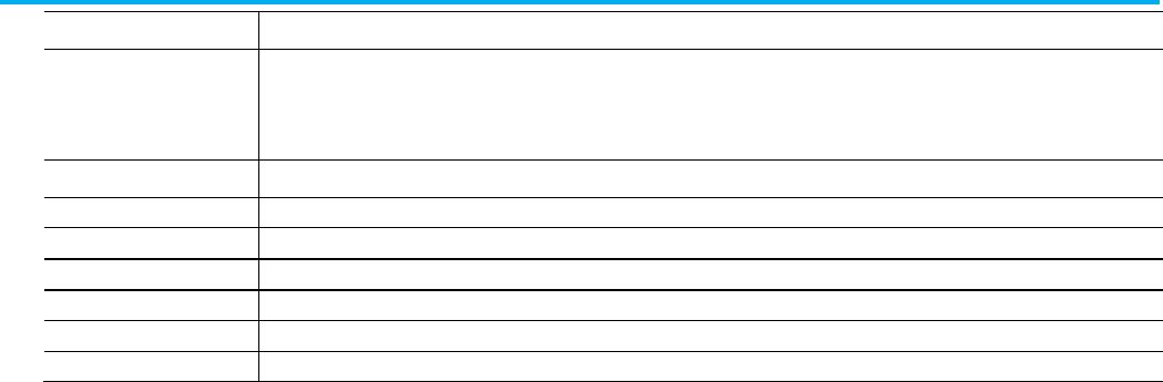
Chapter 9 Define a ladder logic routine
Publication 1756-RM014B-EN-P - November 2023 173
Instruction
Neutral Text Format
TSSM
TSSM(
tssm_tag,restart_type,S1-S2_discrepancy_time,S1_S2-LC_minimum_time,
S1_S2-LC_maximum_time,maximum_mute_time,maximum_override_time,
light_curtain,sensor_1,sensor_2,enable_mute,override,input_status,
muting_lamp_status,reset
);
UID UID();
UIE
UIE();
UPPER
UPPER(
source,destination);
XIC XIC(
data_bit
);
XIO
XIO(
data_bit
);
XOR
XOR(
source_A,source_B,destination
);
XPY
XPY(
source_A,source_B,destination
);

Publication 1756-RM014B-EN-P - November 2023 175
Chapter 10
Define a function block diagram routine
This chapter explains how to enter function block diagram logic in a complete
import/export file.
These examples show the function block routine structure.
Refer to the L5X function block diagram routine structure.
<Routines>
<Routine [Routine_Attributes]>
<Description>
<![CDATA[ text ]]>
</Description>
<FBDContent [FBDContent_Attributes]>
<Sheet [Sheet_Attributes]>
logic
</Sheet>
</FBDContent>
</Routine>
</Routines>
Refer to the L5K Function Block FBD_ROUTINE structure.
FBD_ROUTINE <routine_name> [(Description := "text",
Routine_attributes, FBD_Attributes)]
<function block sheets>
END_FBD_ROUTINE
Function block diagram
routine introduction
Function BlockDiagram
Routine
L5X function block diagram
routine structure
L5K Function Block
FBD_ROUTINE structure
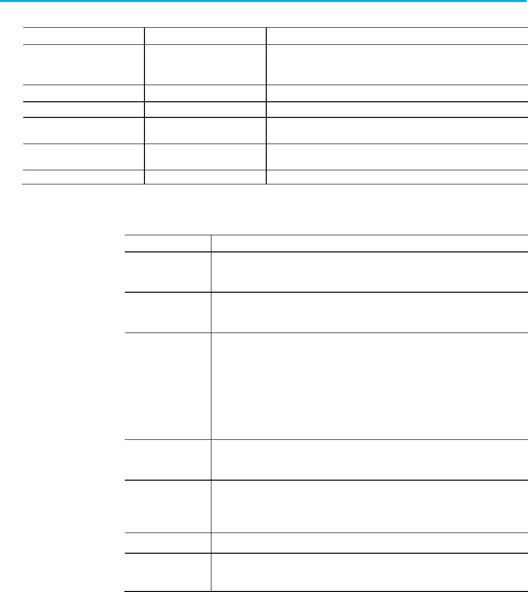
Chapter 10 Define a function block diagram routine
176 Publication 1756-RM014B-EN-P - November 2023
Refer to the L5X and L5K function block routine elements and identities.
L5X Item
L5K Item
Identifies
N/A
routine_name
The name of the routine.
In L5X, use a Name attribute on the <Routine> element.
Description Description User information about the routine.
FBDContent
function block sheets
Function block diagram logic.
EncryptionInfo ENCRYPTION_INFO Details of the license-based Source Protection for the lockable object. Only exists for
protected routines exported in plain text.
EncryptedContent N/A Source Protected and locked routine content. Only exists for locked routines
exported in plain text.
EncryptedSegments
N/A
Locked logic for the routine. Only exists for locked routines exported in plain text.
Refer to the FBD_routine attributes and descriptions.
Attribute
Description
Name L5X only. Specify the name of the routine.
In L5K, the name is an element of the statement.
Type L5X only. Specify FBD.
In L5K, the type of routine is part of the routine statement.
SheetSize Select one of these sizes.
• Letter (8.5x11in)
• Legal (8.5x14in)
• Tabloid (11x17in)
• A4 (210x297mm)
• A3 (297x420mm)
For L5X, this attribute is on the <FBDContent> element.
SheetOrientation Select the orientation of the sheet as Portrait or Landscape.
For L5X, this attribute is on the <FBDContent> element.
OnlineEditType L5X only. Specify the online edit logic type (
Original
,
PendingEdits
, or
TestEdits
). This attribute is not
specified if there are no edits.
For L5X, this attribute is on the <FBDContent> element.
PermissionSet Name of the set of permissions, configured in FactoryTalk Security, to apply to this object.
TrackingGroups The group of tracked objects to which this item belongs. Components can be marked for tracking to
determine whether they have been changed. Version 30 of the Logix Designer application supports
only one tracking group.
Enter the function block diagram logic in sheets within a routine component
in an import/export file.
Refer to the L5X sheet structure.
<Sheet [Sheet_Attributes]>
Function block routine
elements
FBD_routine attributes
Sheet
L5X sheet structure

Chapter 10 Define a function block diagram routine
Publication 1756-RM014B-EN-P - November 2023 177
<Description>
<![CDATA[ text ]]>
</Description>
<IRef [Iref_Attributes]/>
<ORef [Oref_Attributes]/>
<ICon [Icon_Attributes]/>
<OCon [Ocon_Attributes]/>
<Block [Block_Attributes]/>
<AddOnInstruction [AddOnInstruction_Attributes]/>
<JSR [JSR_Attributes]/>
<SBR [SBR_Attributes]/>
<RET [RET_Attributes]/>
<Wire [Wire_Attributes]/>
<FeedbackWire [FeedbackWire_Attributes]/>
<Function [Function_Attributes]/>
<TextBox [TextBox_Attributes]>
text
</TextBox>
<Attachment [Attachment_Attributes]/>
</Sheet>
Refer to the L5K SHEET structure.
SHEET (Name := <sheet_name>)
<IREF declaration>
<OREF declaration>
<ICON declaration>
<OCON declaration>
<mnemonic_BLOCK declaration>
<ADD_ON_INSTRUCTION declaration>
<JSR declaration>
<SBR declaration>
<RET declaration>
<WIRE declaration>
<FEEDBACK_WIRE declaration>
<FUNCTION declaration>
<TEXT_BOX declaration>
<ATTACHMENT declaration>
END_SHEET
Refer to the L5X and L5K elements and identifiers.
L5X Item L5K Item Identifies
L5K SHEET structure
Sheet elements
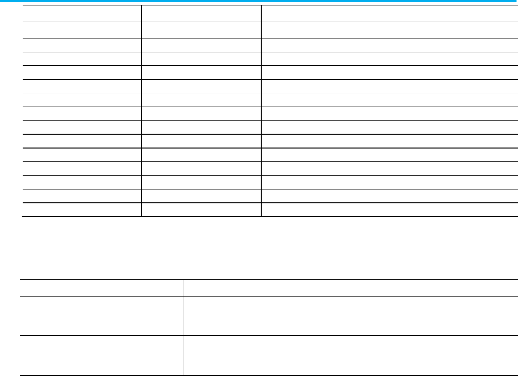
Chapter 10 Define a function block diagram routine
178 Publication 1756-RM014B-EN-P - November 2023
L5X Item
L5K Item
Identifies
IRef
IREF
Input references.
ORef
OREF
Output references.
ICon
ICON
Input wire connectors.
OCon
OCON
Output wire connectors.
Block
mnemonic_BLOCK
Function block instructions and their locations.
AddOnInstruction
ADD_ON_INSTRUCTION
Add-On Instructions.
JSR
JSR
Jump to Subroutine instructions.
SBR
SBR
Subroutine instructions.
RET RET Return instructions.
Wire
WIRE
Wires and their corresponding attachments.
FeedbackWire
FEEDBACK_WIRE
Feedback wires and what they are attached to.
Function
FUNCTION
Function block functions.
TextBox
TEXT_BOX
Text box to hold comments.
Attachment
ATTACHMENT
Attachment from a text box to another function block element.
Refer to the sheet attributes and descriptions.
Attribute
Description
Number
L5X only. Specify the number of the sheet.
In L5K, the sheet number is determined by the order the SHEET statement appears in the L5K format.
Name L5K only. Specify the name of the sheet.
In L5X, the name of the sheet is specified in a <Description> element under the <Sheet> element.
Use these sheet guidelines in your import/export files:
• The sheets in the routine appear in order in the export file. Each sheet
section contains all the drawing elements and wires for that sheet.
• On import, sheet numbers are assigned based on order in the file, not
on the number attribute on the sheet.
• The sheet name is stored as description on the sheet.
• Input references, blocks, output references, special drawing elements,
and wires are contained within the sheet. On export, the elements
appear in the order shown. On import in the L5K format, elements can
be interspersed in the file. On import in the L5X format, the elements
must appear in the exported order.
• Wire and feedback wire statements must appear after all the other
components.
• Be careful when copying and pasting function block components
within an import/export file. Each component within a sheet must
have a unique ID number within that sheet.
Sheet attributes
Sheet guidelines
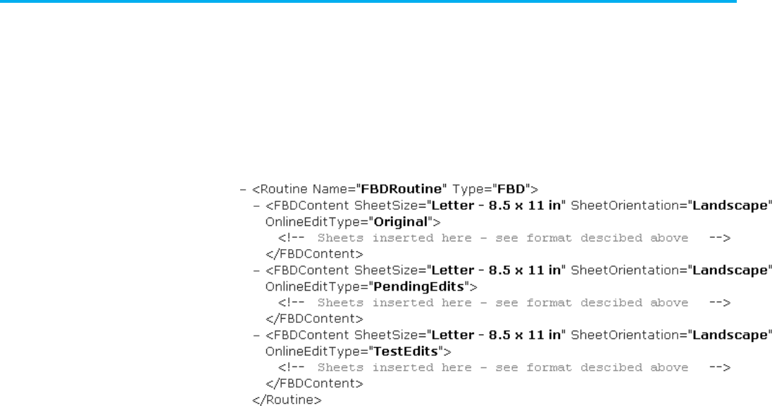
Chapter 10 Define a function block diagram routine
Publication 1756-RM014B-EN-P - November 2023 179
If you export function block logic that contains online edits, the export file
exports LOGIC blocks, in L5K format, or additional <FBDContent> elements,
in L5X format, to indicate the original, test edits, and pending edits states. If
there are no online edits, these LOGIC blocks or additional <FBDContent>
elements are not shown.
L5X Example: Test Edits and Pending Edits Exist
L5K Example 1: Both Test Edits and Pending Edits Exist
FBD_ROUTINE MyFbdRoutine (SheetSize := "Letter
(8.5x11in)", SheetOrientation := Landscape)
LOGIC (Online_Edit_Type := Orig)
(* Sheets inserted here - see format described
above *)
END_LOGIC
LOGIC (Online_Edit_Type := Test)
(* Sheets inserted here - see format described
above *)
END_LOGIC
LOGIC (Online_Edit_Type := Pend)
(* Sheets inserted here - see format described
above *)
END_LOGIC
END_FBD_ROUTINE
L5K Example 2: Only Pending Edits Exist
FBD_ROUTINE MyFbdRoutine (SheetSize := "Letter
(8.5x11in)", SheetOrientation := Landscape)
LOGIC (Online_Edit_Type := Orig)
(* Sheets inserted here - see format described
above *)
Export function block logic
while editing online
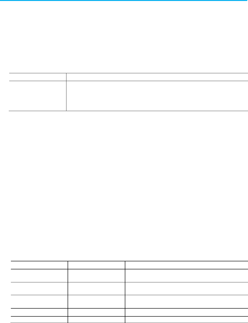
Chapter 10 Define a function block diagram routine
180 Publication 1756-RM014B-EN-P - November 2023
END_LOGIC
LOGIC (Online_Edit_Type := Pend)
(* Sheets inserted here - see format described
above *)
END_LOGIC
END_FBD_ROUTINE
Online Edit Types
Item
Identifies
Online_Edit_Type If online edits exist when the logic is exported, there will be a LOGIC block for Online_Edit_Type := Orig and the appropriate
LOGIC block for the existing edits. Online_Edit_Type : = Pend indicates pending edits. Online_Edit_Type := Test indicates test
edits.
If there are no online edits when the logic is exported, there are no LOGIC blocks and the main components in the routine are
SHEET components.
Input and output references have similar formats and identical attributes.
Refer to the L5X IREF and OREF structure.
<IRef [Reference_Attributes]/>
<ORef [Reference_Attributes]/>
Refer to the L5K IREF and OREF structure.
IREF (Reference_Attributes)
END_IREF
OREF (Reference_Attributes)
END_OREF
Refer to the L5X and L5K reference attributes and identifiers.
L5X Item
L5K Item
Identifies
ID ID The element identifier; uniqueness is important for wiring.
Type an unsigned, 32-bit integer value.
X
X
X-coordinates on internal grid.
Type an unsigned, 32-bit integer value.
Y Y Y-coordinates on internal grid.
Type an unsigned, 32-bit integer value.
Operand Operand Function block instruction.
HideDesc HideDescription Whether or not to hide the description. Specify
true
or
false
.
Input and output references
L5X IREF and OREF
structure
L5K IREF and OREF
structure
Reference attributes

Chapter 10 Define a function block diagram routine
Publication 1756-RM014B-EN-P - November 2023 181
Use these reference guidelines for function blocks:
• If the operand is not a qualified tag or literal value, the reference is not
verified.
• The X and Y grid locations are a relative position from the upper-left
corner of the sheet. X is the horizontal position; Y is the vertical
position.
Input and output wire connectors have similar formats and identical
attributes.
Refer to the L5X ICON and OCON structure.
<ICon [Connector_Attributes]/>
<OCon [Connector_Attributes]/>
Refer to the L5K ICON and OCON structure.
ICON (Connector_Attributes)
END_ICON
OCON (Connector_Attributes)
END_OCON
See the table for .L5X and .L5K items and descriptions.
L5X Item
L5K Item
Identifies
ID ID The element identifier; uniqueness is important for wiring.
Type an unsigned, 32-bit integer value.
X X X-coordinates on internal grid.
Type an unsigned, 32-bit integer value.
Y Y Y-coordinates on internal grid.
Type an unsigned, 32-bit integer value.
Name Name (optional) The name of the wire connector.
Use these connector guidelines for function blocks:
• Output connector names must be unique within a function block
routine.
Reference guidelines
Input and output
connectors
L5X ICON and OCON
structure
L5K ICON and OCON
structure
Connector attributes
Connector guidelines
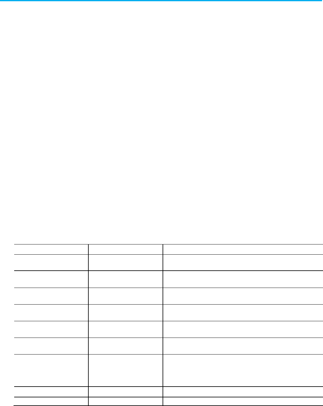
Chapter 10 Define a function block diagram routine
182 Publication 1756-RM014B-EN-P - November 2023
• Multiple input connector names can reference the same output
connector name.
• Input and output connectors with unmatched or blank connector
names are not verified.
• The X and Y grid locations are a relative position from the upper-left
corner of the sheet. X is the horizontal position; Y is the vertical
position.
These examples show block structure.
Refer to the L5X block structure.
<Block [Block_Attributes]>
<Array Name="name", Operand="operand"/>
</Block>
Refer to the L5K BLOCK structure.
mnemonic_BLOCK (Block_Attributes)
END_mnemonic_BLOCK
See the table for .L5X and .L5K items and identifiers.
L5X Item
L5K Item
Identifies
Type
mnemonic
L5X only. The type of Block. Specify the mnemonic name for the block (for example
DEDT
).
ID ID The element identifier; uniqueness is important for wiring.
Type an unsigned, 32-bit integer value.
X X X-coordinates on internal grid.
Type an unsigned, 32-bit integer value.
Y Y Y-coordinates on internal grid.
Type an unsigned, 32-bit integer value.
Operand Operand (optional) Tag name for the block.
For L5X, this attribute is on the <Array> element.
Name ArrayName (optional) Tag name for array.
For L5X , this attribute is on the <Array> element.
VisiblePins VisiblePins List of the names of all the parameters with pins visible for wiring. The names
match the member names on the block tag.
In an .L5X file, separate pin names with spaces.
In an .L5K file, separate pin names with commas.
AutotuneTag AutotuneTag Tag name for the autotune tag.
HideDesc
HideDescription
Whether or not to hide the description. Specify true or false.
Blocks
L5X block structure
L5K BLOCK structure
Block attributes
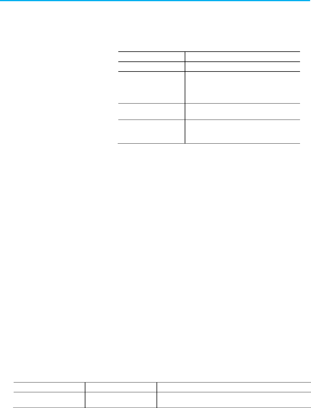
Chapter 10 Define a function block diagram routine
Publication 1756-RM014B-EN-P - November 2023 183
Use these block guidelines with function blocks:
• If the operand is not a qualified tag of the correct data type, the blocks
are not verified.
• Some function block instructions require specific arrays. The table lists
the valid array name for each of these instructions.
Instruction
Array Name
DEDT Storage (required)
FGEN X1 (required)
Y1 (required)
X2 (optional)
Y2 (optional)
MAVE
Storage (required)
Weight (optional)
RMPS RampValue (required)
SoakValue (required)
SoakTime (required)
• The X and Y grid locations are in a relative position from the upper-left
corner of the sheet. X is the horizontal position; Y is the vertical
position.
Function Block functions are similar to instructions but do not require
backing tags, require less memory, sometimes execute more quickly, and take
up less space in a function block diagram. Function Block functions are
available only on CompactLogix 5380, Compact GuardLogix 5380,
CompactLogix 5480, ControlLogix 5580, and GuardLogix 5580 controllers.
Refer to the L5X function structure.
<Function [Function_Attributes]/>
Refer to the L5K FUNCTION structure.
FUNCTION (Function_Attributes)
END_FUNCTION
Refer to the L5X and L5K function attributes and identifiers.
L5X Item
L5K Item
Identifies
Type
mnemonic
L5X only. The type of function. For L5K, specify the mnemonic name for the function
(for example,
ADD
).
Block guidelines
Functions
L5X function structure
L5K FUNCTION structure
Function attributes

Chapter 10 Define a function block diagram routine
184 Publication 1756-RM014B-EN-P - November 2023
L5X Item
L5K Item
Identifies
ID
ID
The element identifier; uniqueness is important for wiring.
Type an unsigned, 32-bit integer value.
X X X-coordinates on internal grid.
Type an unsigned, 32-bit integer value.
Y Y Y-coordinates on internal grid.
Type an unsigned, 32-bit integer value.
The Add-On Instruction elements in a function block diagram routine
structure represent the use of the Add-On Instruction in the routine, not the
definition of the Add-On Instruction.
Refer to the L5X Add-On Instruction structure.
<AddOnInstruction [AddOnInstruction_Attributes]>
<InOutParameter Name="InOutArgument", Argument="argument"/>
</Add0nInstruction>
Refer to the L5K ADD_ON_INSTRUCTION structure.
ADD_ON_INSTRUCTION name (Add_On_Instruction_Attributes)
FBD_PARAMETERS (InOutParmName := InOutArgument, ...)
END_FBD_PARAMETERS
END_ADD_ON_INSTRUCTION
This table contains Add-On Instruction attributes and their descriptions for
Function Block Diagram.
Attribute
Description
Name L5X only. Specify the name of the Add-On Instruction component.
In L5K, the name is an element of the statement.
Class Specify the class of the Add-On Instruction. This attribute applies only to safety projects. Type
Standard
or
Safety
.
Revision Specify the revision of the Add-On Instruction, in the form of MajorRevision.MinorRevision. Each revision
number can be 1...65,535. If there is no period, the number is treated as a major revision only.
RevisionExtension
Provide additional information about the revision (40 characters maximum).
RevisionNote Provide information about the revision (128 characters maximum).
Vendor
Specify the name of the vendor (40 characters maximum) of the Add-On Instruction.
ExecutePrescan Specify whether to execute the Prescan routine after the Logic is prescanned. Type
1
for yes; type
0
for no.
The default is 1 if a Prescan routine exists.
ExecutePostscan Specify whether to execute the Postscan routine after the Logic is postscanned. Type
1
for yes; type
0
for no.
The default is 1 if a Postscan routine exists.
Add-On instructions
L5X Add-On Instruction
structure
L5K ADD_ON_INSTRUCTION
structure
Add-On Instruction
Attributes
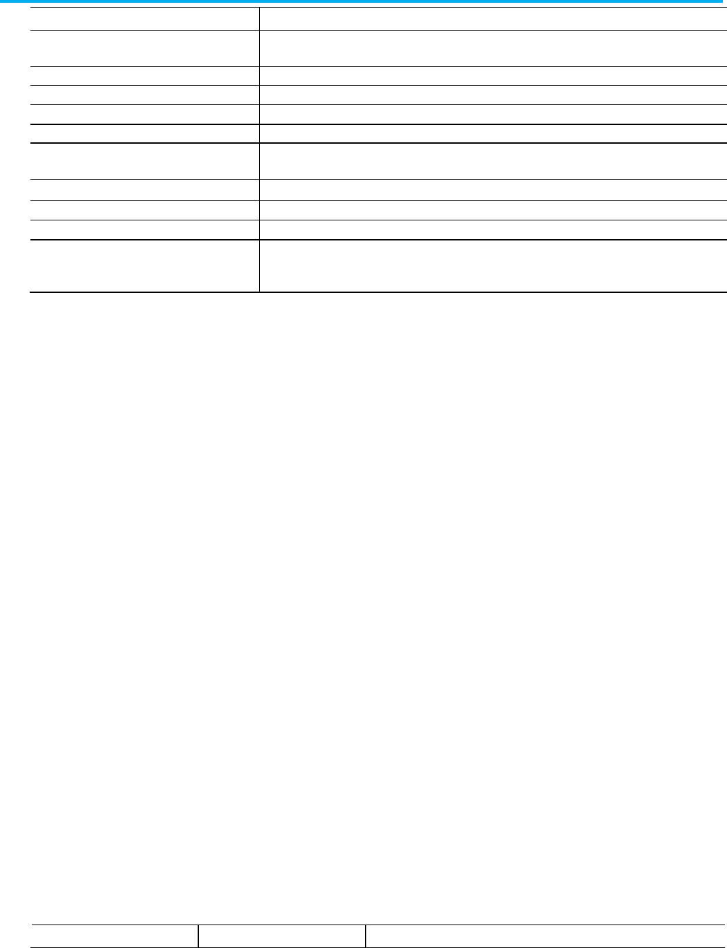
Chapter 10 Define a function block diagram routine
Publication 1756-RM014B-EN-P - November 2023 185
Attribute
Description
ExecuteEnableInFalse
Specify whether to execute the EnableInFalse routine when enable is false. Type 1 for yes; type 0 for no. The
default is 1 if an EnableInFalse routine exists.
CreatedDate
Specify the date the Add-On Instruction was created.
CreatedBy
Specify the developer that created the Add-On Instruction.
EditedDate Specify the date the Add-On Instruction was last edited.
EditedBy
Specify the developer that edited the Add-On Instruction.
SoftwareRevision Specify the revision of the application last used to edit the Add-On Instruction. The default is the currently
open version of the application.
AdditionalHelpText Specify help text specific to the Add-On Instruction.
PermissionSet
Name of the set of permissions, configured in FactoryTalk Security, to apply to this object.
IsEncrypted
Indicates whether the Add-On Instruction is protected with license-based Source Protection and locked.
TrackingGroups The group of tracked objects to which this item belongs. Components can be marked for tracking to determine
whether they have been changed. Version 30 of the Logix Designer application supports only one tracking
group.
Use these Add-On Instruction guidelines with function blocks:
• If the operand is not a qualified tag or literal value, the Add-On
Instruction is not verified.
• The X and Y grid locations are a relative position from the upper-left
corner of the sheet. X is the horizontal position; Y is the vertical
position.
The JSR section consists of:
• L5X JSR structure
• L5K JSR structure
• JSR attributes
• JSR guidelines
Refer to the JSR [JSR_Attributes] structure.
<JSR [JSR_Attributes]>
</JSR>
Refer to the L5K JSR structure.
JSR (JSR_Attributes)
END_JSR
Refer to the L5X and L5K attributes and identifiers.
L5X Item
L5K Item
Identifies
Add-On Instruction
Guidelines
JSR
L5X JSR structure
L5K JSR structure
JSR attributes
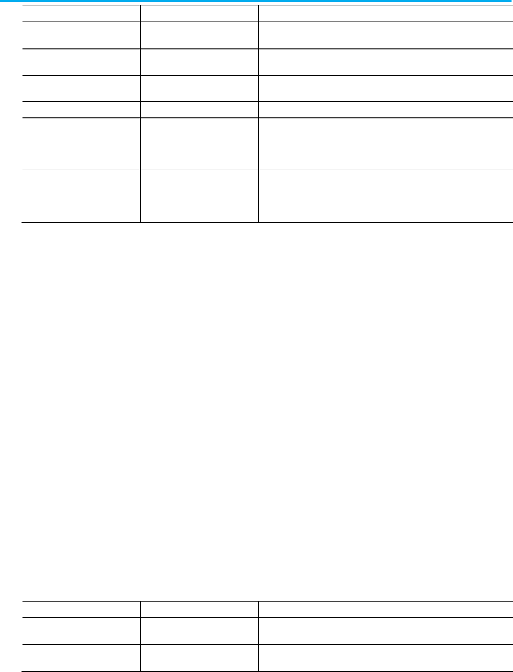
Chapter 10 Define a function block diagram routine
186 Publication 1756-RM014B-EN-P - November 2023
L5X Item
L5K Item
Identifies
ID
ID
The element identifier; uniqueness is important for wiring.
Type an unsigned, 32-bit integer value.
X X X-coordinates on internal grid.
Type an unsigned, 32-bit integer value.
Y Y Y-coordinates on internal grid.
Type an unsigned, 32-bit integer value.
Routine Routine Specify the JSR routine name.
In In Specify the input parameters.
In an .L5X file, separate input parameter names with spaces.
In an .L5K file, separate input parameter names with commas.
Ret
Ret
Specify the return parameters.
In an .L5X file, separate return parameter names with spaces.
In an .L5K file, separate return parameter names with commas.
The X and Y grid locations are a relative position from the upper-left corner of
the sheet. X is the horizontal position; Y is the vertical position.
The SBR section consists of:
• L5X SBR structure
• L5K SBR structure
• SBR attributes
• SBR guidelines
Refer to the L5X SBR structure.
<SBR [SBR_Attributes]>
</SBR>
Refer to the L5K SBR structure.
SBR (SBR_Attributes)
END_SBR
Refer to the L5X and L5K SBR attributes and identifiers.
L5X Item
L5K Item
Identifies
ID ID The element identifier; uniqueness is important for wiring.
Type an unsigned, 32-bit integer value.
X X X-coordinates on internal grid.
Type an unsigned, 32-bit integer value.
JSR guidelines
SBR
L5X SBR structure
L5K SBR structure
SBR attributes
Chapter 10 Define a function block diagram routine
Publication 1756-RM014B-EN-P - November 2023 187
L5X Item
L5K Item
Identifies
Y
Y
Y-coordinates on internal grid.
Type an unsigned, 32-bit integer value.
Routine
Routine
Specify the SBR routine name.
Ret Ret Specify the return parameters.
In an .L5X file, separate return parameter names with spaces.
In an .L5K file, separate return parameter names with commas.
The X and Y grid locations are a relative position from the upper-left corner of
the sheet. X is the horizontal position; Y is the vertical position.
The RET section consists of:
• L5X RET structure
• L5K RET structure
• RET attributes
• RET guidelines
Refer to the L5X RET structure.
<RET [RET_Attributes]>
</RET>
Refer to the L5K RET structure.
RET (RET_Attributes)
END_RET
Refer to the L5X and L5K RET attributes and identifiers.
L5X Item
L5K Item
Identifies
ID ID The element identifier; uniqueness is important for wiring.
Type an unsigned, 32-bit integer value.
X X X-coordinates on internal grid.
Type an unsigned, 32-bit integer value.
Y Y Y-coordinates on internal grid.
Type an unsigned, 32-bit integer value.
Routine Routine Specify the JSR routine name.
In In Specify the input parameters.
In an .L5X file, separate input parameter names with spaces.
In an .L5K file, separate input parameter names with commas.
SBR guidelines
RET
L5X RET structure
L5K RET structure
RET attributes

Chapter 10 Define a function block diagram routine
188 Publication 1756-RM014B-EN-P - November 2023
The X and Y grid locations are a relative position from the upper-left corner of
the sheet. X is the horizontal position; Y is the vertical position.
The wire and feedback wire formats describe a wire by specifying what it is
attached to at each end, which is always a pin on another drawing element.
Refer to the L5X wire structure.
<Wire [Wire_Attributes]/>
<FeedbackWire [Wire_Attributes]/>
Refer to the L5K Wire structure.
WIRE (Wire_Attributes)
END_WIRE
FEEDBAK_WIRE (Wire_Attributes)
END_FEEDBACK_WIRE
Refer to the L5X and L5K wire attributes and identifiers.
L5X Item
L5K Item
Identifies
FromID FromElementID The source drawing element.
Type an unsigned, 32-bit integer.
FromParam FromParameter The pin on the source drawing element.
For: Type:
Blocks Parameter name
Irefs In
Icons In
ToID ToElementID The destination drawing element.
Type an unsigned, 32-bit integer.
ToParam ToParameter The pin on the destination drawing element.
For: Type:
Blocks Parameter name
Orefs Out
Ocons Out
Use these wire guidelines:
• Wires that are not correctly specified are not imported.
RET guidelines
Wires and feedback wires
L5X wire structure
L5K WIRE structure
Wire attributes
Wire guidelines
Chapter 10 Define a function block diagram routine
Publication 1756-RM014B-EN-P - November 2023 189
• A feedback wire follows the same format as a wire. Just connect the
Source and Destination elements to form a feedback wire.
The text box blocks in an SFC routine hold descriptions about SFC
components.
Refer to the L5X TextBox structure.
<TextBox [TextBoxAttributes]>
<![CDATA[ text ]] >
</TextBox>
Refer to the L5K TEXTBOX structure.
TEXT_BOX (Text_Box_Attributes,
Text := <"text">)
END_TEXT_BOX
Refer to the L5X and L5K text box attributes and identifiers.
L5X Item
L5K Item
Identifies
ID ID The element identifier; uniqueness is important for wiring.
Type an unsigned, 32-bit integer value.
X
X
X-coordinates on internal grid.
Type an unsigned, 32-bit integer value.
Y
Y
Y-coordinates on internal grid.
Type an unsigned, 32-bit integer value.
Width
Width
This attribute is not currently used; it is there for future use. Type 0.
Text
Text
The descriptive text.
Use these guidelines for text boxes:
• All text box blocks must come after all block sections.
• Text boxes can be free-standing or they can be attached to
FBD elements.
The attachment blocks identify the attachments from text boxes to other
function block elements.
Text boxes
L5X TextBox structure
L5K TEXTBOX structure
Text box attributes
Text box guidelines for
block sections
Function block attachments
Chapter 10 Define a function block diagram routine
190 Publication 1756-RM014B-EN-P - November 2023
Refer to the L5X attachment structure.
<Attachment [Attachment_Attributes]/>
Refer to the L5K ATTACHMENT structure.
ATTACHMENT (Attachment_Attributes)
END_ATTACHMENT
See the table for .L5X and .L5K items and identifiers.
L5X Item
L5K Item
Identifies
FromID FromElementID The ID of the attached object. Type an unsigned, 32-bit integer
value.
ToID ToElementID The ID of the object that the FromID object is attached to. Type
an unsigned, 32-bit integer value.
Use these guidelines for attachments:
• Use an attachment to link a text box to an FBD element.
• All attachment blocks must come after all text box blocks.
L5X Function Block Diagram Example
L5X attachment structure
L5K ATTACHMENT structure
Attachment attributes
FBD element attachment
guidelines
Attachments examples
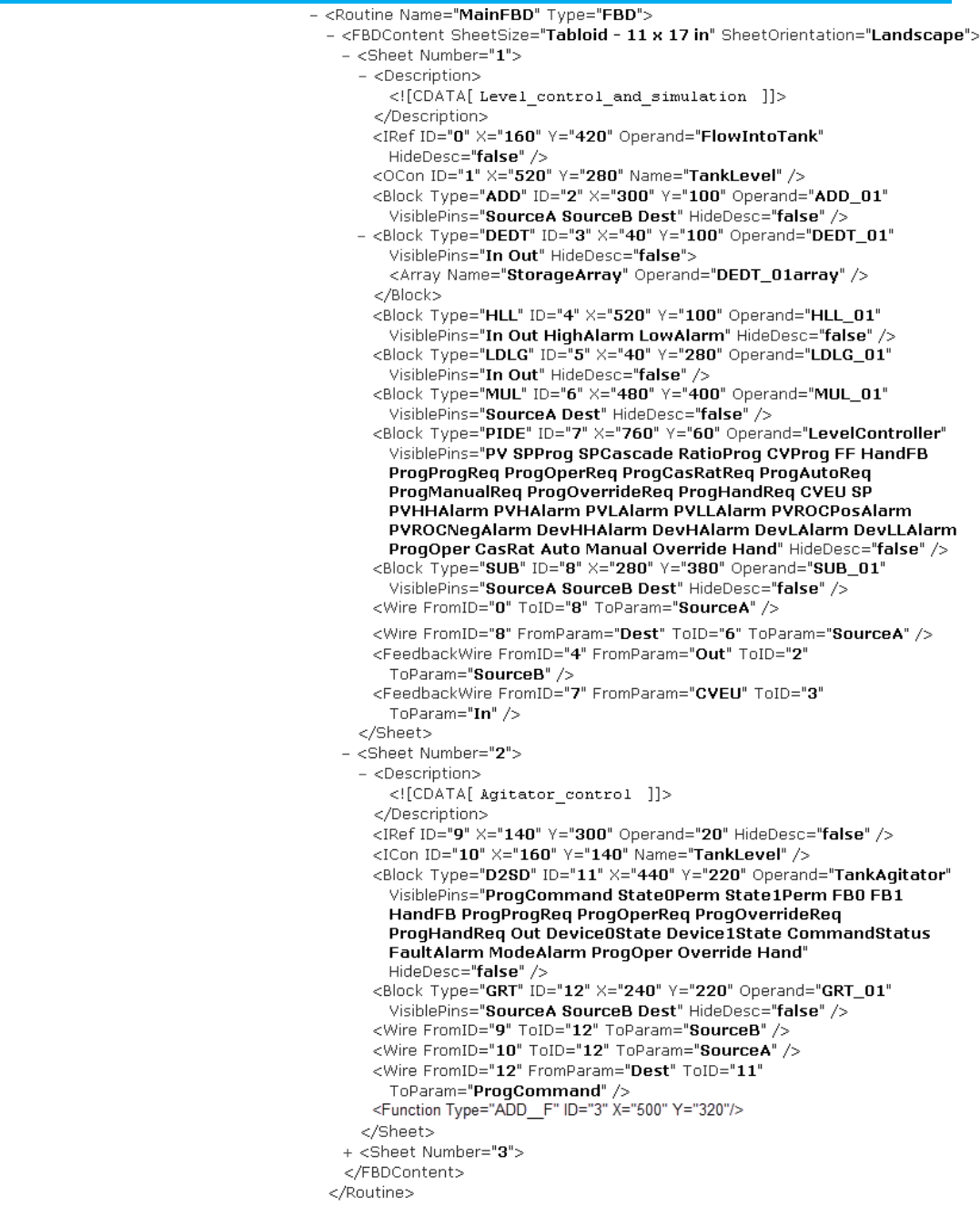
Chapter 10 Define a function block diagram routine
Publication 1756-RM014B-EN-P - November 2023 191

Chapter 10 Define a function block diagram routine
192 Publication 1756-RM014B-EN-P - November 2023
L5K FBD_ROUTINE Example
FBD_ROUTINE My_FBD_Routine (SheetSize := "Tabloid
(11x17in)", SheetOrientation := Landscape)
SHEET (Name := Input_Scaling)
IREF (ID := 3,
X := 120,
Y := 120,
Operand := Input_Tag)
END_IREF
OREF (ID := 5,
X := 520,
Y := 320,
Operand := Output_Tag)
END_OREF
ICON (ID := 4,
X := 160,
Y := 320,
Name := ConnectorName)
END_ICON
OCON (ID := 6,
X := 680,
Y := 100,
Name := ConnectorName)
END_OCON
MUL_BLOCK (ID := 0,
X := 440,
Y := 60,
Operand := MUL_01,
VisiblePins := "SourceA, SourceB,
Dest")
END_MUL_BLOCK
SCL_BLOCK (ID := 1,
X := 240,
Y := 60,
Operand := SCL_01,
VisiblePins := "In, InEUMax, Out,
MaxAlarm")
END_SCL_BLOCK
PI_BLOCK (ID := 2,
X := 260,

Chapter 10 Define a function block diagram routine
Publication 1756-RM014B-EN-P - November 2023 193
Y := 260,
Operand := PI_01,
VisiblePins := "In, Initialize,
InitialValue, Out, HighAlarm, LowAlarm")
END_PI_BLOCK
WIRE (FromElementID := 3,
FromParameter := "",
ToElementID := 1,
ToParameter := In)
END_WIRE
WIRE (FromElementID := 4,
FromParameter := "",
ToElementID := 2,
ToParameter := In)
END_WIRE
WIRE (FromElementID := 0,
FromParameter := Dest,
ToElementID := 6,
ToParameter := "")
END_WIRE
WIRE (FromElementID := 1,
FromParameter := Out,
ToElementID := 0,
ToParameter := SourceA)
END_WIRE
WIRE (FromElementID := 2,
FromParameter := Out,
ToElementID := 5,
ToParameter := "")
END_WIRE
FEEDBACK_WIRE (FromElementID := 0,
FromParameter := Dest,
ToElementID := 0,
ToParameter := SourceB)
END_FEEDBACK_WIRE
ADD_FUNCTION (ID := 13,
X := 340,
Y := 120)
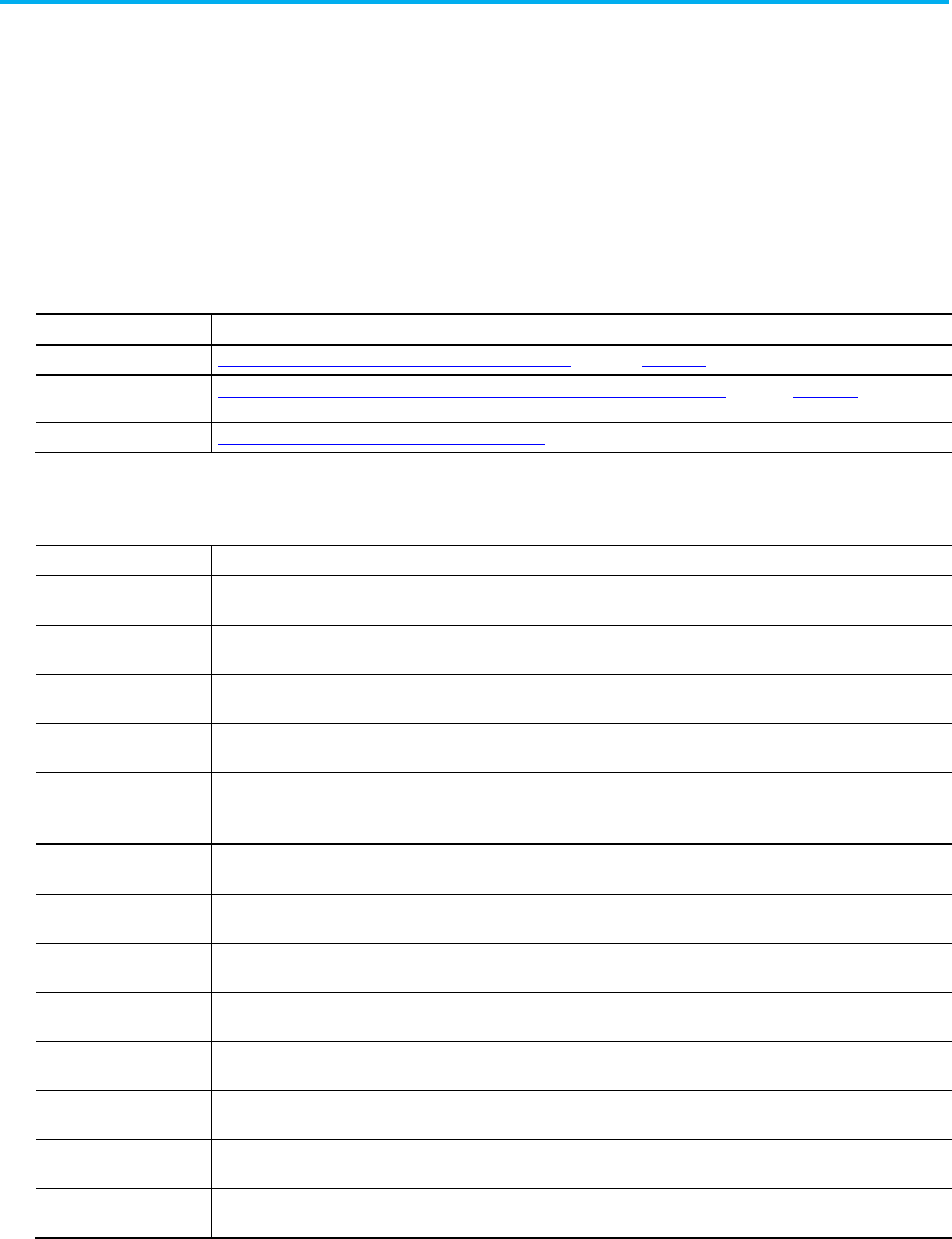
Chapter 10 Define a function block diagram routine
194 Publication 1756-RM014B-EN-P - November 2023
END_ADD_FUNCTION
END_SHEET
END_FBD_ROUTINE
These tables list each function block instruction and its format in the Block
component of an import/export file. For details about a specific instruction,
see the listed reference manuals.
Function block instruction reference manuals
Instruction Type Resource
Basic, sequential instruction Logix5000 Controllers General Instructions Set Reference Manual, publication 1756-RM003
.
Process control or drives
instruction
Logix5000 Controllers Advanced Process Control and Drives Instruction Set Reference Manual
,
publication1756-RM006
.
Motion instruction Logix5000 Controllers Motion Instructions Reference Manual, publication-RM002.
Function block instructions
Instruction
Default Operand and VisiblePins formats (components within the Block structure)
ABS Operand := ABS_01,
VisiblePins := "
Source, Destination
")
ACS Operand := ACS_01,
VisiblePins := "
Source, Destination"
)
ADD Operand := ADD_01,
VisiblePins := "
SourceA, SourceB, Destination"
)
ALM Operand := ALM_01,
VisiblePins := "
In, HHAlarm, HAlarm, LAlarm, LLAlarm, ROCPosAlarm, ROCNegAlarm
")
ALMA Operand := ALMA_01,
VisiblePins := "
In, HHInAlarm, HInAlarm, LInAlarm, LLInAlarm, ROCPosInAlarm, ROCNegInAlarm, HHAcked, HAcked, LAcked, LLAcked,
ROCPosAcked, ROCNegAcked, Suppressed, Disabled
")
ALMD Operand := ALMD_01,
VisiblePins := "
In, InAlarm, Acked, Suppressed, Disabled
")
AND Operand := AND_01,
VisiblePins := "S
ourceA, SourceB, Destination
")
ASN Operand := ASN_01,
VisiblePins := "S
ource, Destination
")
ATN Operand := ATN_01,
VisiblePins := "S
ource, Destination"
)
BAND Operand := BAND_01,
VisiblePins := "
In1, In2, In3, In4, Out
")
BNOT Operand := BNOT_01,
VisiblePins := "
In, Out
")
BOR Operand := BOR_01,
VisiblePins := "
In1, In2, In3, In4, Out
")
BTDT Operand := BTDT_01,
VisiblePins :=
"Source, SourceBit, Length, DestBit, Target, Dest"
)
Parameters for function
block instructions

Chapter 10 Define a function block diagram routine
Publication 1756-RM014B-EN-P - November 2023 195
Instruction
Default Operand and VisiblePins formats (components within the Block structure)
BXOR
Operand := BXOR_01,
VisiblePins := "
In1, In2, Out
")
COS
Operand := COS_01,
VisiblePins := "
Source, Dest
")
CTUD
Operand := CTUD_01,
VisiblePins := "C
UEnable, CDEnable, PRE, Reset, ACC, DN"
)
D2SD
Operand := D2SD_01,
VisiblePins := "
ProgCommand, State0Perm, State1Perm, FB0, FB1, HandFB, ProgProgReq, ProgOperReq, ProgOverrideReq, ProgHandReq,
Out, Device0State, Device1State, CommandStatus, FaultAlarm, ModeAlarm, ProgOper, Override, Hand"
)
D3SD Operand := D3SD_01,
VisiblePins := "
Prog0Command, Prog1Command, Prog2Command, State0Perm, State1Perm, State2Perm, FB0, FB1, FB2, FB3, HandFB0,
HandFB1, HandFB2, ProgProgReq, ProgOperReq, ProgOverrideReq, ProgHandReq, Out0, Out1, Out2, Device0State, Device1State,
Device2State, Command0Status, Command1Status, Command2Status, FaultAlarm, ModeAlarm, ProgOper, Override, Hand"
)
DEDT Operand := DEDT_01,
VisiblePins := "
In, Out
",
Storage :=
array_name
)
DEG Operand := DEG_01,
VisiblePins := "
Source, Dest
")
DERV Operand := DERV_01,
VisiblePins := "
In, ByPass, Out
")
DFF Operand := DFF_01,
VisiblePins := "
D, Clear, Clock, Q, QNot
")
DIV Operand := DIV_01,
VisiblePins := "
SourceA, SourceB, Dest"
)
ESEL Operand := ESEL_01,
VisiblePins := "
In1, In2, In3, In4, In5, In6, ProgSelector, ProgProgReq, ProgOperReq, ProgOverrideReq, Out, SelectedIn, ProgOper,
Override
")
EQU Operand := EQU_01,
VisiblePins := "
SourceA, SourceB"
)
FGEN Operand := FGEN_01,
VisiblePins := "
In, Out
",
X1 :=
array_name
,
X2 :=
array_name
,
Y2 :=
array_name
,
Y2 :=
array_name
)
FRD Operand := FRD_01,
VisiblePins := "
Source, Dest"
)
GEQ Operand := GEQ_01,
VisiblePins := "
SourceA, SourceB"
)
GRT Operand := GRT_01,
VisiblePins := "
SourceA, SourceB"
)
HLL Operand := HLL_01,
VisiblePins := "
In, Out, HighAlarm, LowAlarm
")
HPF Operand := HPF_01,
VisiblePins := "
In, Out
")
INTG Operand := INTG_01,
VisiblePins := "
In, Out
")
JKFF Operand := JKFF_01,
VisiblePins := "
Clear, Clock, Q, QNot
")

Chapter 10 Define a function block diagram routine
196 Publication 1756-RM014B-EN-P - November 2023
Instruction
Default Operand and VisiblePins formats (components within the Block structure)
LEQ
Operand := LEQ_01,
VisiblePins := "
SourceA, SourceB"
)
LES
Operand := LES_01,
VisiblePins := "
SourceA, SourceB"
)
LIM
Operand := LIM_01,
VisiblePins := "
LowLlimit, Test, HighLimit"
)
LN
Operand := LN_01,
VisiblePins := "
Source, Dest"
)
LOG Operand := LOG_01,
VisiblePins := "
Source, Dest"
)
LPF Operand := LPF_01,
VisiblePins := "
In, Out
")
MAVE Operand := MAVE_01,
VisiblePins := "
In, Out
",
Storage :=
array_name
,
Weight :=
array_name
)
MAXC Operand := MAXC_01,
VisiblePins := "
In, Reset, ResetValue, Out
")
MEQ Operand := MEQ_01,
VisiblePins := "
Source, Mask, Compare"
)
MINC Operand := MINC_01,
VisiblePins := "
In, Reset, ResetValue, Out
")
MOD Operand := MOD_01,
VisiblePins := "
SourceA, SourceB, Dest"
)
MSTD
Operand := MSTD_01,
VisiblePins := "
In, SampleEnable, Out
",
Storage :=
array_name
)
MUL Operand := MUL_01,
VisiblePins := "
SourceA, SourceB, Dest"
)
MUX Operand := MUX_01,
VisiblePins := "
In1, In2, In3, In4, In5, In6, In7, In8, Selector, Out
")
MVMT Operand := MVMT_01,
VisiblePins := "
Source, Mask, Target, Dest"
)
NEG
Operand := NEG_01,
VisiblePins := "
Source, Dest"
)
NEQ
Operand := NEQ_01,
VisiblePins := "
SourceA, SourceB"
)
NOT
Operand := NOT_01,
VisiblePins := "
Source, Dest"
)
NTCH
Operand := NTCH_01,
VisiblePins := "
In, Out
")
OR
Operand := OR_01,
VisiblePins := "
SourceA, SourceB, Dest"
)
OSFI
Operand := OSFI_01,
VisiblePins := "
InputBit, OutputBit"
)
OSRI Operand := OSRI_01,
VisiblePins := "
InputBit, OutputBit
")
PI Operand := PI_01,
VisiblePins := "
In, Out
")

Chapter 10 Define a function block diagram routine
Publication 1756-RM014B-EN-P - November 2023 197
Instruction
Default Operand and VisiblePins formats (components within the Block structure)
PIDE
Operand := PIDE_01,
VisiblePins := "
PV, SPProg, SPCascade, RatioProg, CVProg, FF, HandFB, ProgProgReq, ProgOperReq, ProgCasRatReq, ProgAutoReq,
ProgManuaReq, ProgOverrideReq, ProgHandReq, CVEU, SP, PVHHAlarm, PVHAlarm, PVLAlarm, PVLLAlarm, PVROCPosAlarm,
PVROCNegAlarm, DevHHAlarm, DevHAlarm, DevLAlarm, DevLLAlarm, ProgOper, CasRat, Auto, Manual, Override, Hand
")
PMUL Operand := PMUL_01,
VisiblePins := "
In, Multipler, Out
")
POSP Operand := POSP_01,
VisiblePins := "
SP, Position, OpenedFB, ClosedFB, OpenOut, CloseOut
")
RAD Operand := RAD_01,
VisiblePins := "
Source, Dest"
)
RESD Operand := RESD_01,
VisiblePins := "
Set, Reset, Out, OutNot
")
RLIM Operand := RLIM_01,
VisiblePins := "
In, ByPass, Out
")
RMPS Operand := RMPS_01,
VisiblePins := "
PV, CurrentSegProg, OutProg, SoakTimeProg, ProgProgReq, ProgOperReq, ProgAutoReq, ProgManualReq, ProgHoldReq,
Out, CurrentSeg, SoakTimeLeft, GuarRampOn, GuarSoakOn, ProgOper, Auto, Manual, Hold
",
RampValue :=
array_name
,
SoakValue :=
array_name
,
SoakTime :=
array_name
)
RTOR Operand := RTOR_01,
VisiblePins :=
TimerEnable, PRE, Reset, ACC, DN")
SCL Operand := SCL_01,
VisiblePins := "
In, Out
")
SCRV Operand := SCRV_01,
VisiblePins := "
In, Out
")
SEL Operand := SEL_01,
VisiblePins := "
In1, In2, SelectorIn, Out
")
SETD Operand := SETD_01,
VisiblePins := "
Set, Reset, Out, OutNot
")
SIN Operand := SIN_01,
VisiblePins := SIN(
source,destination
);
SNEG Operand := SNEG_01,
VisiblePins := "
In, NegateEnable, Out
")
SOC Operand := SOC_01,
VisiblePins := "
In, Out
")
SQR Operand := SQR_01,
VisiblePins := "
Source, Dest"
)
SRTP Operand := SRTP_01,
VisiblePins := "
In, HeatOut, CoolOut, HeatTimePercent, CoolTimePercent
")
SSUM Operand := SSUM_01,
VisiblePins := "
In1, Select1, In2, Select2, In3, Select3, In4, Select4, Out
")
SUB Operand := SUB_01,
VisiblePins := "
SourceA, SourceB, Dest"
)
TAN Operand := TAN_01,
VisiblePins := "
Source, Dest")
TOD Operand := TOD_01,
VisiblePins := "
Source, Dest")
TOFR Operand := TOFR_01,
VisiblePins := "
TimerEnable, PRE, Reset, ACC, DN
")
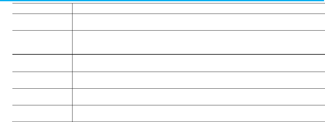
Chapter 10 Define a function block diagram routine
198 Publication 1756-RM014B-EN-P - November 2023
Instruction
Default Operand and VisiblePins formats (components within the Block structure)
TONR
Operand := TONR_01,
VisiblePins := "
TimerEnable, PRE, Reset, ACC, DN
")
TOT
Operand := TOT_01,
VisiblePins := "
In, ProgProgReq, ProgOperReq, ProgStartReq, ProgStopReq, ProgResetReq, Total, OldTotal, ProgOper, RunStop,
ProgResetDone, TargetFlag, TargetDev1Flag, TargetDev2Flag
")
TRN Operand := TRN_01,
VisiblePins := "
Source, Dest")
UPDN
Operand := UPDN_01,
VisiblePins := "
InPlus, InMinus, Out
")
XOR
Operand := XOR_01,
VisiblePins := "
SourceA, SourceB, Dest"
)
XPY
Operand := XPY_01,
VisiblePins := "
SourceA, SourceB, Dest"
)

Publication 1756-RM014B-EN-P - November 2023 199
Chapter 11
Define a sequential function chart routine
This chapter explains how to enter sequential function chart logic in a
complete import/export file.
For more information on creating sequential function charts and correct
syntax, see the Logix5000 Controller Common Procedures Programming
Manual, publication 1756-PM001.
These examples show sequential function chart structure.
Refer to the L5X sequential function chart structure.
<Routines>
<Routine [Routine_Attributes]>
<Description>
<![CDATA[ text ]]>
</Description>
<SFCContent [SFCContent_Attributes]>
<Step [Step_Attributes]/>
<Transition [Transition_Attributes]/>
<Branch [Branch_Attributes]/>
<SbrRet [SbrRet_Attributes]/>
<Stop [Stop_Attributes]/>
<Branch [Branch_Attributes]/>
<DirectedLink
[DirectedLink_Attributes]/>
<TextBox [TextBox_Attributes]>
text
</TextBox>
<Attachment [Attachment_Attributes]/>
</SFCContent>
</Routine>
</Routines>
Sequential function chart
routine introduction
Sequential function chart
routine
L5X sequential function
chart structure

Chapter 11 Define a sequential function chart routine
200 Publication 1756-RM014B-EN-P - November 2023
Refer to the L5K sequential function SFC_ROUTINE chart structure.
SFC_ROUTINE <routine_name> [(Routine_Attributes,
SFC_Attributes)]
<STEP declaration>
<TRANSITION declaration>
<BRANCH declaration>
<SBR_RET declaration>
<STOP declaration>
<BRANCH declaration>
<DIRECTED_LINK declaration>
<TEXT_BOX declaration)
<ATTACHMENT declaration>
END_SFC_ROUTINE
Refer to the L5X and L5K sequential function chart elements and identifiers.
L5X Item
L5K Item
Identifies
N/A
routine_name
The name of the routine.
In L5X, use a Name attribute on the <Routine> element.
Description Description User information about the routine.
SFCContent
N/A
Sequential function chart logic.
EncryptionInfo
ENCRYPTION_INFO
Details of the license-based Source Protection for the lockable object. Only exists for
protected routines exported in plain text.
EncryptedContent
N/A
Source Protected and locked routine content. Only exists for locked routines
exported in plain text.
EncryptedSegments N/A Locked logic for the routine. Only exists for locked routines exported in plain text.
Refer to the SFC_Routine attributes and descriptions.
Attribute
Description
Name L5X only. Specify the name of the routine.
For L5K, the name is an element of the statement.
Type L5X only. Specify SFC.
In L5K, the type of routine is part of the routine statement.
SheetSize The size of the SFC. Select one of these options.
• Letter (8.5x11in)
• Legal (8.5x14in)
• Tabloid (11x17in)
• A4 (210x297mm)
• A3 (297x420mm)
In L5X, this attribute is on the <SFCContent> element.
L5K sequential function
chart SFC_ROUTINE
structure
Sequential function chart
elements
SFC_Routine attributes
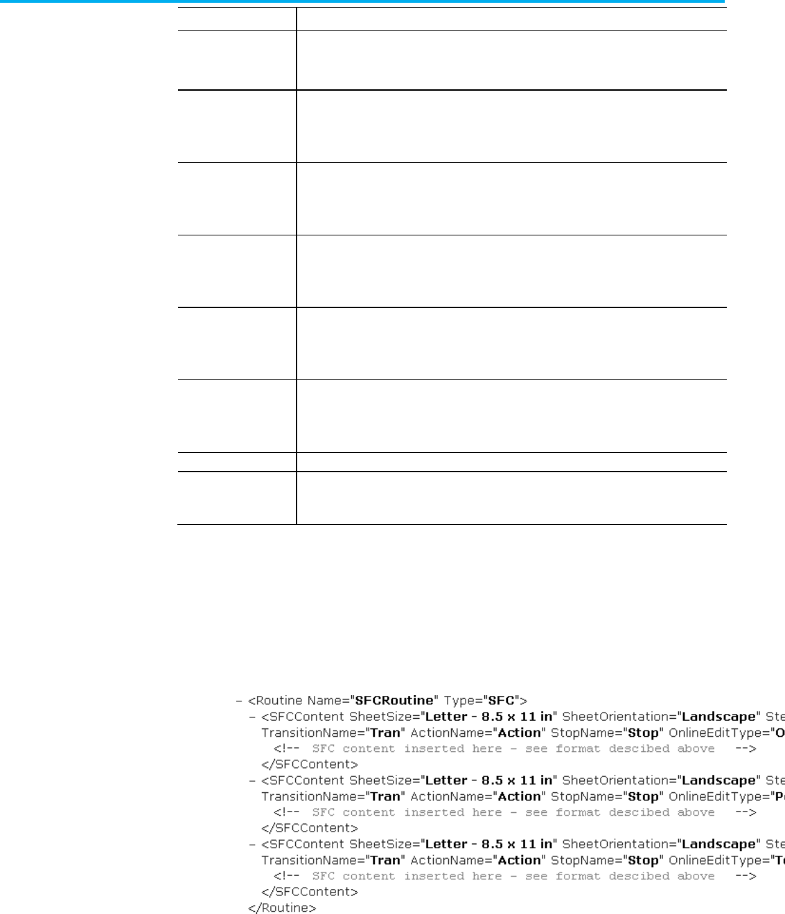
Chapter 11 Define a sequential function chart routine
Publication 1756-RM014B-EN-P - November 2023 201
Attribute
Description
SheetOrientation
The orientation of the SFC sheet. Select Portrait or Landscape.
In L5X, this attribute is on the <SFCContent> element.
StepName The prefix for the name of the step blocks within this SFC routine. The Logix Designer application
uses this prefix when it automatically generates an SFC_STEP tag.
In L5X, this attribute is on the <SFCContent> element.
TransitionName The prefix for the name of the transition blocks with this SFC routine. The Logix Designer application
uses this prefix when it automatically generates a transition tag.
In L5X, this attribute is on the <SFCContent> element.
ActionName The prefix for the name of the action blocks in this SFC routine. The Logix Designer application uses
this prefix when it automatically generates an SFC_ACTION tag.
In L5X, this attribute is on the <SFCContent> element.
StopName The prefix for the name of the stop blocks in this SFC routine. The Logix Designer application uses
this prefix when it automatically generates an SFC_STOP tag.
In L5X, this attribute is on the <SFCContent> element.
OnlineEditType L5X only. Specify the online edit logic type (
Original
,
PendingEdits
, or
TestEdits
). This attribute is not
specified if there are no edits.
In L5X, this attribute is on the <SFCContent> element.
PermissionSet
Name of the set of permissions, configured in FactoryTalk Security, to apply to this object.
TrackingGroups The group of tracked objects to which this item belongs. Components can be marked for tracking to
determine whether they have been changed. Version 30 of the Logix Designer application supports
only one tracking group.
If you export sequential function chart logic that contains online edits, the
export file exports LOGIC blocks (in L5K format) or additional <SFCContent>
elements (in L5X format) to indicate the original, test edits, and pending edits
states. If there are no online edits, you will not see these LOGIC blocks or
additional <SFCContent> elements.
L5X Example: Test edits and pending edits exist
Export sequential function
chart logic while editing
online

Chapter 11 Define a sequential function chart routine
202 Publication 1756-RM014B-EN-P - November 2023
L5K Example 1: Both test edits and pending edits exist
SFC_ROUTINE MySFCRoutine (SheetSize := "Letter
(8.5x11in)",
SheetOrientation := Landscape, StepName := "Step",
TransitionName := "Tran", ActionName := "Action",
StopName := "Stop")
LOGIC (Online_Edit_Type := Orig)
(* SFC logic here *)
END_LOGIC
LOGIC (Online_Edit_Type := Test)
(* SFC logic here *)
END_LOGIC
LOGIC (Online_Edit_Type := Pend)
(* SFC logic here *)
END_LOGIC
END_SFC_ROUTINE
L5K Example 2: Only pending edits exist
SFC_ROUTINE MySFCRoutine (SheetSize := "Letter
(8.5x11in)",
SheetOrientation := Landscape, StepName := "Step",
TransitionName := "Tran", ActionName := "Action",
StopName := "Stop")
LOGIC (Online_Edit_Type := Orig)
(* SFC logic here *)
END_LOGIC
LOGIC (Online_Edit_Type := Pend)
(* SFC logic here *)
END_LOGIC
END_SFC_ROUTINE
Online edit types
Item
Identifies
Online_Edit_Type When you export logic:
• If online edits exist, there is a LOGIC block for Online_Edit_Type := Orig and the appropriate LOGIC block for the existing edits.
Online_Edit_Type : = Pend indicates pending edits. Online_Edit_Type := Test indicates test edits.
• If there are no online edits when you export the logic, there are no LOGIC blocks and the main components in the routine are SFC
logic components.

Chapter 11 Define a sequential function chart routine
Publication 1756-RM014B-EN-P - November 2023 203
These examples show the step structure.
Refer to the L5X step structure.
<Step [Step_Attributes]>
<Preset>
logic
</Preset>
<LimitHigh>
logic
</LimitHigh>
<LimitLow>
logic
</LimitLow>
<Action>
logic
</Action>
</Step>
Refer to the L5K STEP structure.
STEP (Step_Attributes)
<PRESET declaration>
<LIMIT_HIGH declaration>
<LIMIT_LOW declaration>
<ACTION_LIST declaration>
END_STEP
L5X Item
L5K Item
Identifies
Preset
PRESET
A structured text expression that specifies the preset time in milliseconds for the
step timer. If the PresetUsesExpression attribute (above) is
Yes
, type preset logic.
LimitHigh LIMIT_HIGH A structured text expression that specifies the preset time in milliseconds for a limit
high alarm. If the LimitHighUsesExpression attribute (above) is
Yes
, type limit high
logic.
LimitLow LIMIT_LOW A structured text expression that specifies the preset time in milliseconds for a limit
low alarm. If the LimitLowUsesExpression attribute (above) is
Yes
, type limit low
logic.
ActionList ACTION_LIST The actions in the step.
Steps
SFC L5X step structure
SFC L5K STEP structure
Step elements

Chapter 11 Define a sequential function chart routine
204 Publication 1756-RM014B-EN-P - November 2023
L5X Item
L5K Item
Identifies
ID
ID
The step identifier. This ID uniquely identifies this step from all other blocks. Type
an unsigned, 32-bit integer value.
X
X
X-coordinate on internal grid. Type an unsigned, 32-bit integer value.
Y Y Y-coordinate on internal grid. Type an unsigned, 32-bit integer value.
Operand Operand The step tag. Type a tag of datatype SFC_STEP. The import process uses this tag
name to name the step.
HideDesc HideDescription Whether or not to hide the step description. Type
Yes
or
No
.
DescX DescriptionX X-coordinate on internal grid of the description box. Type an unsigned,
32-bit integer value.
DescY
DescriptionY
Y-coordinate on internal grid of the description box. Type unsigned, 32-bit integer
value.
DescWidth DescriptionWidth This attribute is not currently used; it is there for future use. Type
0
.
InitialStep InitialStep Whether this step is the initial step of the routine. Type
Yes
or
No
.
If you have multiple steps identified as the initial step, which is incorrect syntax, the
import process designates the last initial step it encounters as the initial step and
removes the initial step indicators from any other steps.
PresetUsesExpr PresetUsesExpression Whether the preset for the step timer is a structured text expression. Type
Yes
if
you plan to enter an expression in a preset element, otherwise, type No.
LimitHighUsesExpr LimitHighUsesExpression Whether the preset for the limit high alarm is a structured text expression. Type
Yes
if you plan to enter an expression in a limit high element, otherwise, type
No
.
LimitLowUsesExpr LimitLowUsesExpression Whether the preset for the limit low alarm is a structured text expression. Type
Yes
if you plan to enter an expression in a limit low element, otherwise, type No.
ShowActions ShowActions Whether to show or hide the step’s actions. Type
Yes
or
No
.
The preset component contains a structured text expression that specifies the
preset time in milliseconds for the step timer.
Refer to the L5X present structure.
<Preset>
<STContent>
<Line Number="number">
<![CDATA[ structured_text; ]]>
</Line>
</STContent>
</Preset>
Refer to the L5K PRESET structure.
PRESET (LanguageType := ST)
‘<structured_text>
SFC step attributes
Preset
L5X preset structure
L5K PRESET structure

Chapter 11 Define a sequential function chart routine
Publication 1756-RM014B-EN-P - November 2023 205
END_PRESET
Each line of L5K structured text begins with a single quote (‘).
The limit high component contains a structured text expression that specifies
the preset time in milliseconds for a limit high alarm.
Refer to the L5X limit high structure.
<LimitHigh>
<STContent>
<Line Number="0">
<![CDATA[ structured_text; ]]>
</Line>
</STContent>
</LimitHigh>
Refer to the L5K LIMITHIGH structure.
LIMITLOW (LanguageType := ST)
‘<structured_text>
END_LIMITLOW
Each line of L5K structured text begins with a single quote (‘).
The limit low component contains a structured text expression that specifies
the preset time in milliseconds for a limit low alarm.
Refer to the L5X limit low structure.
<LimitLow>
<STContent>
<Line Number="0">
<![CDATA[ structured_text; ]]>
</Line>
</STContent>
</LimitLow>
Refer to the L5K LIMITHIGH structure.
Limit high
L5X limit high structure
L5K LIMITHIGH structure
Limit low
L5X limit low structure
L5K LIMITHIGH structure

Chapter 11 Define a sequential function chart routine
206 Publication 1756-RM014B-EN-P - November 2023
LIMITLOW (LanguageType := ST)
‘<structured_text>
END_LIMITLOW
Each line of L5K structured text begins with a single quote (‘).
Each step can contain multiple actions.
Refer to the L5X Action structure.
<Action [Action_Attributes]>
<Preset>
logic
</Preset>
<Body>
logic
</Body>
</Action>
Refer to the L5K ACTION structure.
ACTION (Action_Attributes)
<PRESET declaration>
<BODY declaration>
END_ACTION
Use the table to view the action attributes for L5X and L5K items.
L5X Item
L5K Item
Identifies
ID ID The action identifier. This ID uniquely identifies this action from all other blocks.
Enter an unsigned, 32-bit integer value.
Operand Operand The action tag. Enter a tag of datatype SFC_ACTION. The import process uses this
tag name to name the action.
Action list
L5X Action structure
L5K ACTION structure
Action attributes
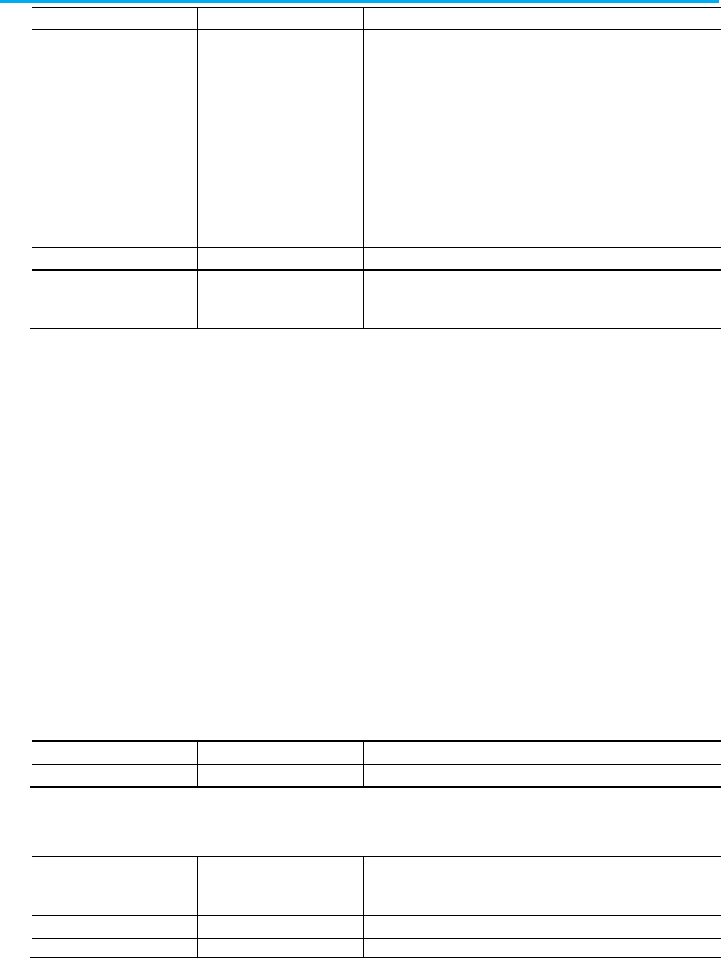
Chapter 11 Define a sequential function chart routine
Publication 1756-RM014B-EN-P - November 2023 207
L5X Item
L5K Item
Identifies
Qualifier Qualifier The action qualifier:
N - non-stored
R - reset
S - stored
L - time limited
D - time delayed
P - pulse
P1 - pulse (rising edge)
P0 - pulse (falling edge)
SL - stored and time limited
SD - stored and time delayed
DS - time delayed and stored
IsBoolean IsBoolean Whether or not the action is boolean. Enter Yes or No.
PresetUsesExpr PresetUsesExpression Whether the preset for the action timer is a structured text expression. Enter Yes if
you plan to enter an expression in a PRESET block, otherwise, enter No.
IndicatorTag IndicatorTag The indicator tag. Enter tag.
These examples show transition structure.
Refer to the L5X transition structure.
<Transition [Transition_Attributes]>
<Condition>
logic
</Condition>
</Transition>
Refer to the L5K TRANSITION structure.
TRANSITION (Transition_Attributes)
<CONDITION declaration>
END_TRANSITION
Refer to the L5X and L5K transition element and identifier.
L5X Item
L5K Item
Identifies
Condition CONDITION The condition to evaluate for the transition.
Refer to the L5X and L5K transition attributes and identifiers.
L5X Item
L5K Item
Identifies
ID ID The step identifier. This ID uniquely identifies this step from all other blocks. Type
an unsigned, 32-bit integer value.
X X X-coordinate on internal grid. Type an unsigned, 32-bit integer value.
Y
Y
Y-coordinate on internal grid. Type an unsigned, 32-bit integer value.
Transitions
L5X transition structure
L5K TRANSITION structure
Transition elements
Transition attributes
Chapter 11 Define a sequential function chart routine
208 Publication 1756-RM014B-EN-P - November 2023
L5X Item
L5K Item
Identifies
Operand
Operand
The step tag. Type a tag of datatype SFC_STEP. The import process uses this tag
name to name the step.
HideDesc HideDescription Whether or not to hide the step description. Type
Yes
or
No
.
DescX DescriptionX X-coordinate on internal grid of the description box. Type an unsigned,
32-bit integer value.
DescY DescriptionY Y-coordinate on internal grid of the description box. Type unsigned, 32-bit integer
value.
DescWidth
DescriptionWidth
This attribute is not currently used; it is there for future use. Type 0.
Force Force The transition is forced. Type
true
for forced true (set) or type
false
for forced false
(cleared). If the transition is not forced, do not enter this attribute.
The condition component uses a structured text expression to specify a
condition to evaluate for the transition.
Refer to the L5X condition structure.
<Condition>
<STContent>
<Line Number="0">
<![CDATA[ structured_text; ]]>
</Line>
</STContent>
</Condition>
Refer to the L5K CONDITION structure.
CONDITION (LanguageType := ST)
‘<structured_text>
END_CONDITION
Each line of L5K structured text begins with a single quote (‘).
Subroutine calls pass values into and out of the SFC routine.
Refer to the L5X SbrRet structure.
<SbrRet [Subroutine_Attributes]/>
Condition
L5X condition structure
L5K CONDITION structure
Subroutine calls
L5X SbrRet structure
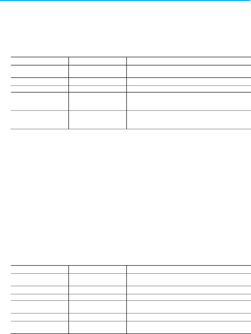
Chapter 11 Define a sequential function chart routine
Publication 1756-RM014B-EN-P - November 2023 209
Refer to the L5K SBR_RET structure.
SBR_RET (Subroutine_Attributes)
END_SBR_RET
Refer to the L5X and L5K subroutine attributes and identifiers.
L5X Item
L5K Item
Identifies
ID ID The SBR_RET identifier. This ID uniquely identifies this subroutine call from all other
blocks. Type an unsigned, 32-bit integer value.
X X X-coordinate on internal grid. Type an unsigned, 32-bit integer value.
Y
Y
Y-coordinate on internal grid. Type an unsigned, 32-bit integer value.
In In List of values to receive from the calling routine. Type list of tags or literal values
and separate each entry by a comma (,). Enter empty quotes if there are no values to
receive.
Ret Out List of values to pass to the calling routine. Type list of tags or literal values and
separate each entry by a comma (,). Enter empty quotes if there are no values to
pass.
These examples show stop structure.
Refer to the L5X stop structure.
<Stop [StopAttributes]/>
Refer to the L5K STOP structure.
STOP (Stop_Attributes)
END_STOP
Refer to the L5X and L5K stop attributes and identifiers.
L5X Item
L5K Item
Identifies
ID ID The stop identifier. This ID uniquely identifies this stop from all other blocks. Type
an unsigned, 32-bit integer value.
X X X-coordinate on internal grid. Type an unsigned, 32-bit integer value.
Y
Y
Y-coordinate on internal grid. Type an unsigned, 32-bit integer value.
Operand Operand The stop tag. Type a tag of datatype SFC_STOP. The import process uses this tag
name to name the stop.
HideDesc HideDescription Whether or not to hide the stop description. Type
Yes
or
No
.
DescX DescriptionX X-coordinate on internal grid of the description box. Type an unsigned,
32-bit integer value.
L5K SBR_RET structure
Subroutine attributes
Stops
L5X stop structure
L5K STOP structure
Stop attributes
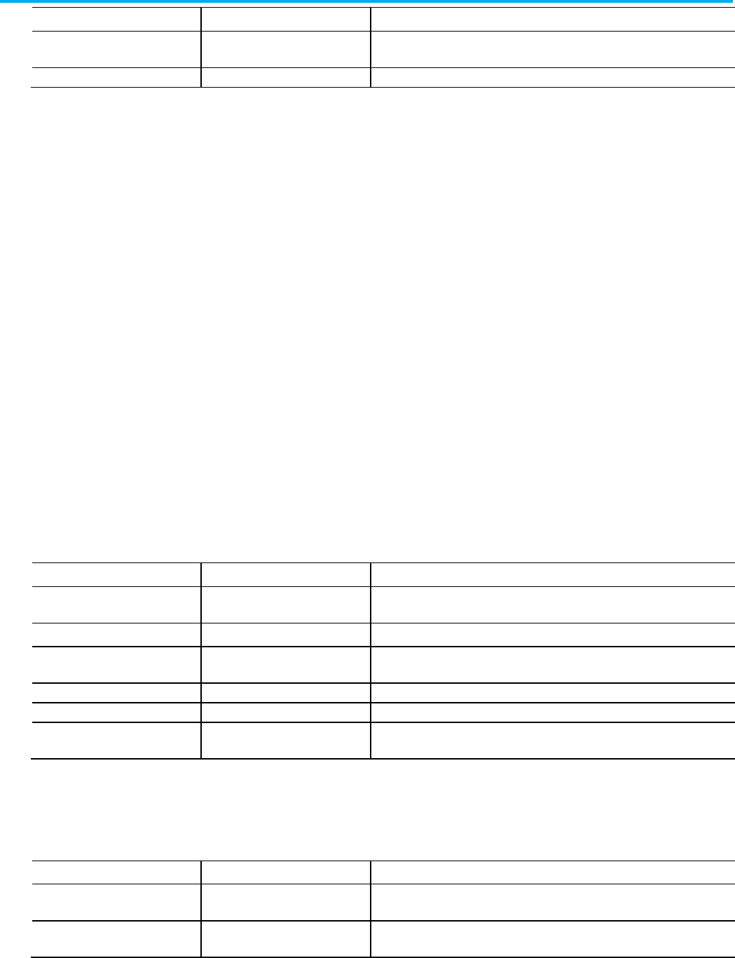
Chapter 11 Define a sequential function chart routine
210 Publication 1756-RM014B-EN-P - November 2023
L5X Item
L5K Item
Identifies
DescY
DescriptionY
Y-coordinate on internal grid of the description box. Type unsigned, 32-bit integer
value.
DescWidth
DescriptionWidth
This attribute is not currently used; it is there for future use. Type 0.
The branch blocks in an SFC routine identify simultaneous or selection
branches in the routine.
Refer to the L5X branch structure.
<Branch [BranchAttributes]>
<Leg [LegAttributes]/>
</Branch>
Refer to the L5K BRANCH structure.
BRANCH (Branch_Attributes)
LEG (Leg_Attributes)
END_LEG
END_BRANCH
See the table for .L5X and .L5K items and identifiers.
L5X Item
L5K Item
Identifies
ID
ID
The branch identifier. This ID uniquely identifies this branch from all other blocks.
Type an unsigned, 32-bit integer value.
X X X-coordinate on internal grid. Type an unsigned, 32-bit integer value.
Y Y Y-coordinate on internal grid. Type an unsigned, 32-bit integer value.
BranchType BranchType The type of branch. Type
Simultaneous
or
Selection
.
BranchFlow BranchFlow The direction of the branch. Type
Converge
or
Diverge
.
Priority Priority Whether the priority of a divergent selection branch is defined by the user. This
attribute applies only to divergent selection branches. Type
Default
or
UserDefined
.
Refer to the L5X and L5K let attributes and identifiers.
L5X Item
L5K Item
Identifies
ID ID The leg identifier. This ID uniquely identifies this leg from all other blocks. Type an
unsigned, 32-bit integer value.
Force Force Whether the leg is forced or not. You can force only a leg in a simultaneous branch.
Omit this attribute, for no forces, or type false to force the leg false.
SFC routine branches
L5X branch structure
L5K BRANCH structure
Branch attributes
Leg attributes
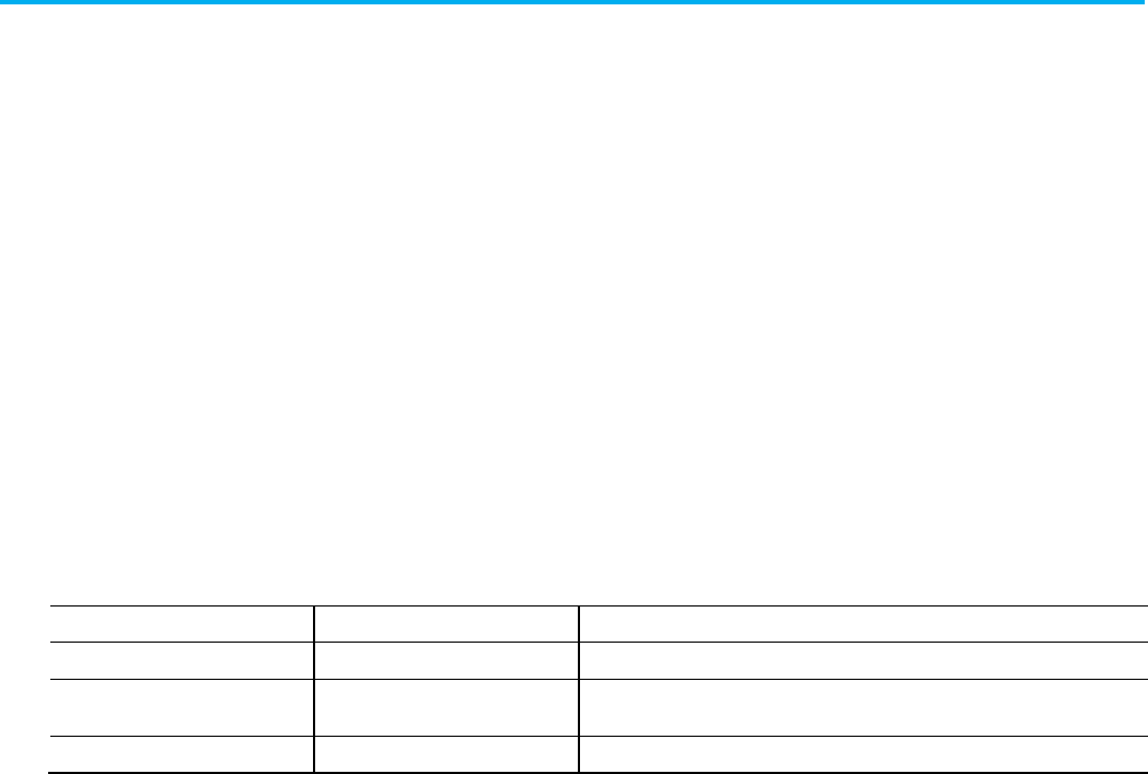
Chapter 11 Define a sequential function chart routine
Publication 1756-RM014B-EN-P - November 2023 211
The directed link blocks in an SFC routine identify the links between SFC
components.
Refer to the L5X DirectedLink structure.
<DirectedLink [DirectedLinkAttributes]/>
Refer to the L5K DIRECTED_LINK structure.
DIRECTED_LINK (Directed_Link_Attributes)
END_DIRECTED_LINK
See the table for direct link attributes .L5X and .L5K items and identifiers.
L5X Item
L5K Item
Identifies
FromID FromElementID The ID of the object. Type an unsigned, 32-bit integer value.
ToID ToElementID The ID of the object that the FromID object is attached to. Type an unsigned, 32-bit
integer value.
Show ShowLink Whether or not to show the link. Type
TRUE
or
FALSE
.
Use these guidelines for directed links:
• All directed link blocks must come after all step, transition, stop, and
branch blocks.
• A directed link links only one element to one other element.
The text box blocks in an SFC routine hold descriptions about SFC
components.
Refer to the L5X TextBox structure.
<TextBox [TextBoxAttributes]>
<![CDATA[ text ]] >
</TextBox>
Refer to the L5K TEXTBOX structure.
SFC directed links
L5X DirectedLink structure
L5K DIRECTED_LINK
structure
Directed link attributes
Directed link guidelines
Text boxes
L5X TextBox structure
L5K TEXTBOX structure
Chapter 11 Define a sequential function chart routine
212 Publication 1756-RM014B-EN-P - November 2023
TEXT_BOX (Text_Box_Attributes,
Text := <"text">)
END_TEXT_BOX
Refer to the L5X and L5K text box attributes and identifiers.
L5X Item
L5K Item
Identifies
ID ID The element identifier; uniqueness is important for wiring.
Type an unsigned, 32-bit integer value.
X
X
X-coordinates on internal grid.
Type an unsigned, 32-bit integer value.
Y
Y
Y-coordinates on internal grid.
Type an unsigned, 32-bit integer value.
Width
Width
This attribute is not currently used; it is there for future use. Type 0.
Text
Text
The descriptive text.
Use these guidelines for text boxes:
• All text box blocks must come after all directed link blocks.
• Text boxes can be free-standing or they can be attached to
SFC elements.
The attachment blocks in an SFC routine identify the attachments from text
boxes to other SFC elements.
Refer to the L5X attachment structure.
<Attachment [Attachment_Attributes]/>
Refer to the L5K ATTACHMENT structure.
ATTACHMENT (Attachment_Attributes)
END_ATTACHMENT
See the table for .L5X and .L5K items and identifiers.
L5X Item
L5K Item
Identifies
FromID FromElementID The ID of the attached object. Type an unsigned, 32-bit integer
value.
ToID ToElementID The ID of the object that the FromID object is attached to. Type
an unsigned, 32-bit integer value.
Text box attributes
Text box guidelines for
directed link blocks
Attachments
L5X attachment structure
L5K ATTACHMENT structure
Attachment attributes
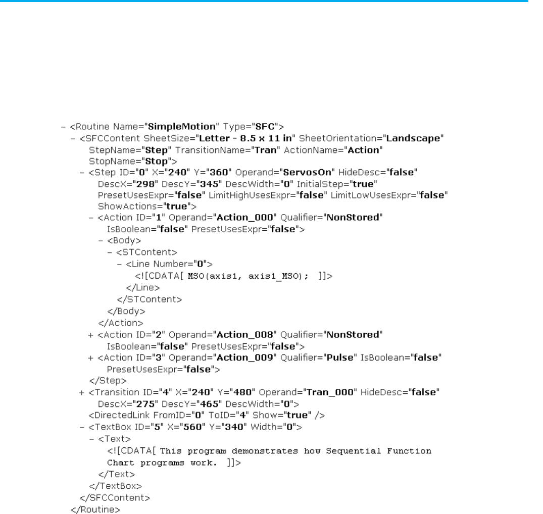
Chapter 11 Define a sequential function chart routine
Publication 1756-RM014B-EN-P - November 2023 213
Use these guidelines for attachments:
• Use an attachment to link a text box to an SFC element.
• All attachment blocks must come after all text box blocks.
L5X sequential function chart example
L5K SFC_ROUTINE Example
SFC element attachment
guidelines
SFC attachments examples
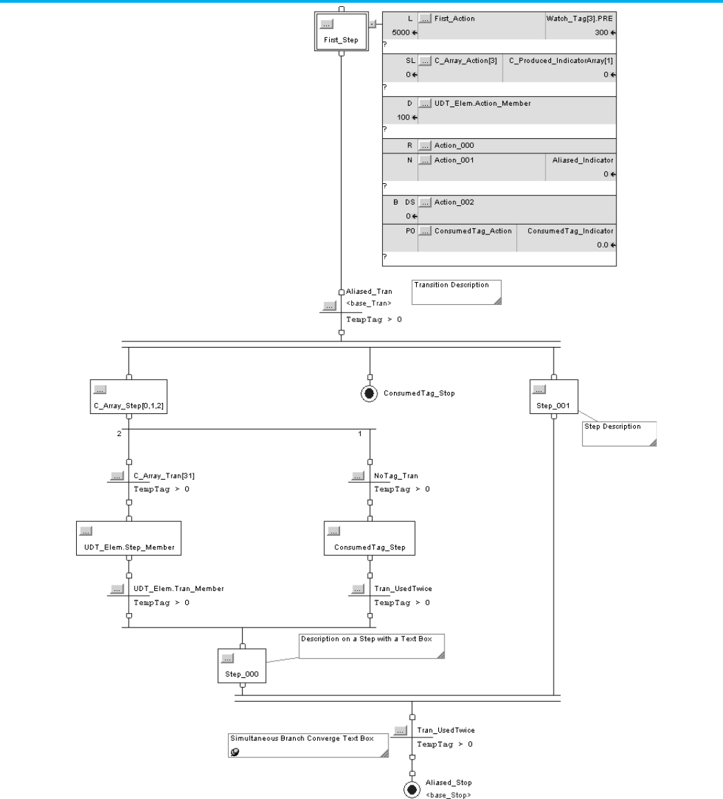
Chapter 11 Define a sequential function chart routine
214 Publication 1756-RM014B-EN-P - November 2023
SFC_ROUTINE Sample_SFC_Routine1 (SheetSize := "Letter
(8.5x11in)",
SheetOrientation := Landscape, StepName :=
"Step",
TransitionName := "Tran", ActionName :=
"Action",
StopName := "Stop")

Chapter 11 Define a sequential function chart routine
Publication 1756-RM014B-EN-P - November 2023 215
TRANSITION (ID := 0, X := 120, Y := 1000, Operand :=
C_Array_Tran[31],
HideDescription := Yes, DescriptionX := 155,
DescriptionY := 985,
DescriptionWidth := 0)
CONDITION (LanguageType := ST)
'TempTag > 0
END_CONDITION
END_TRANSITION
BRANCH (ID := 2, Y := 820, BranchType := Simultaneous,
BranchFlow := Diverge)
LEG (ID := 3)
END_LEG
LEG (ID := 4)
END_LEG
LEG (ID := 5)
END_LEG
END_BRANCH
TRANSITION (ID := 6, X := 420, Y := 760, Operand :=
Aliased_Tran,
HideDescription := No, DescriptionX := 520,
DescriptionY := 740,
DescriptionWidth := 0)
CONDITION (LanguageType := ST)
'TempTag > 0
END_CONDITION
END_TRANSITION
STOP (ID := 8, X := 460, Y := 880, Operand :=
ConsumedTag_Stop,
HideDescription := Yes, DescriptionX := 565,
DescriptionY := 865,
DescriptionWidth := 0)
END_STOP
TRANSITION (ID := 10, X := 520, Y := 1360, Operand :=
Tran_UsedTwice,
HideDescription := Yes, DescriptionX := 555,
DescriptionY := 1345,
DescriptionWidth := 0)
CONDITION (LanguageType := ST)
'TempTag > 0
END_CONDITION
END_TRANSITION
TRANSITION (ID := 12, X := 460, Y := 1160, Operand :=
Tran_UsedTwice,
HideDescription := Yes, DescriptionX := 495,
DescriptionY := 1145,
DescriptionWidth := 0)
CONDITION (LanguageType := ST)

Chapter 11 Define a sequential function chart routine
216 Publication 1756-RM014B-EN-P - November 2023
'TempTag > 0
END_CONDITION
END_TRANSITION
BRANCH (ID := 14, Y := 940, BranchType := Selection,
BranchFlow := Diverge,
Priority := UserDefined)
LEG (ID := 15)
END_LEG
LEG (ID := 16)
END_LEG
END_BRANCH
BRANCH (ID := 17, Y := 1320, BranchType :=
Simultaneous, BranchFlow := Converge)
LEG (ID := 18)
END_LEG
LEG (ID := 19)
END_LEG
END_BRANCH
STOP (ID := 20, X := 520, Y := 1440, Operand :=
Aliased_Stop, HideDescription := No,
DescriptionX := 400, DescriptionY := 1480,
DescriptionWidth := 0)
END_STOP
STEP (ID := 22, X := 420, Y := 360, Operand :=
First_Step, HideDescription := Yes,
DescriptionX := 478, DescriptionY := 345,
DescriptionWidth := 0,
InitialStep := Yes, PresetUsesExpression := No,
LimitHighUsesExpression := No,
LimitLowUsesExpression := No, ShowActions :=
Yes)
ACTION (ID := 24, Operand := First_Action,
Qualifier := L, IsBoolean := No,
PresetUsesExpression := No, IndicatorTag :=
Watch_Tag[3].PRE)
BODY (LanguageType := ST)
'
END_BODY
END_ACTION
ACTION (ID := 25, Operand := C_Array_Action[3],
Qualifier := SL,
IsBoolean := No, PresetUsesExpression := No,
IndicatorTag := C_Produced_IndicatorArray[1])
BODY (LanguageType := ST)
'
END_BODY
END_ACTION

Chapter 11 Define a sequential function chart routine
Publication 1756-RM014B-EN-P - November 2023 217
ACTION (ID := 26, Operand :=
UDT_Elem.Action_Member, Qualifier := D,
IsBoolean := No, PresetUsesExpression := No,
IndicatorTag := "")
BODY (LanguageType := ST)
'
END_BODY
END_ACTION
ACTION (ID := 27, Operand := Action_000,
Qualifier := R, IsBoolean := No,
PresetUsesExpression := No, IndicatorTag := "")
BODY (LanguageType := ST)
'
END_BODY
END_ACTION
ACTION (ID := 28, Operand := Action_001,
Qualifier := N, IsBoolean := No,
PresetUsesExpression := No, IndicatorTag :=
Aliased_Indicator)
BODY (LanguageType := ST)
'
END_BODY
END_ACTION
ACTION (ID := 29, Operand := Action_002,
Qualifier := DS, IsBoolean := Yes,
PresetUsesExpression := No, IndicatorTag := "")
END_ACTION
ACTION (ID := 30, Operand :=
ConsumedTag_Action, Qualifier := P0,
IsBoolean := No, PresetUsesExpression := No,
IndicatorTag := ConsumedTag_Indicator)
BODY (LanguageType := ST)
'
END_BODY
END_ACTION
END_STEP
STEP (ID := 31, X := 120, Y := 880, Operand :=
"C_Array_Step[0,1,2]",
HideDescription := Yes, DescriptionX := 179,
DescriptionY := 865,
DescriptionWidth := 0, InitialStep := No,
PresetUsesExpression := No,
LimitHighUsesExpression := No,
LimitLowUsesExpression := No, ShowActions := Yes)
END_STEP
TRANSITION (ID := 33, X := 460, Y := 1000, Operand :=
NoTag_Tran,

Chapter 11 Define a sequential function chart routine
218 Publication 1756-RM014B-EN-P - November 2023
HideDescription := Yes, DescriptionX := 495,
DescriptionY := 985,
DescriptionWidth := 0)
CONDITION (LanguageType := ST)
'TempTag > 0
END_CONDITION
END_TRANSITION
STEP (ID := 35, X := 120, Y := 1080, Operand :=
UDT_Elem.Step_Member,
HideDescription := Yes, DescriptionX := 199,
DescriptionY := 1065,
DescriptionWidth := 0, InitialStep := No,
PresetUsesExpression := No,
LimitHighUsesExpression := No,
LimitLowUsesExpression := No, ShowActions := Yes)
END_STEP
STEP (ID := 37, X := 720, Y := 880, Operand := Step_001,
HideDescription := No,
DescriptionX := 760, DescriptionY := 940,
DescriptionWidth := 0,
InitialStep := No, PresetUsesExpression := No,
LimitHighUsesExpression := No,
LimitLowUsesExpression := No, ShowActions :=
Yes)
END_STEP
BRANCH (ID := 39, Y := 1220, BranchType := Selection,
BranchFlow := Converge)
LEG (ID := 40)
END_LEG
LEG (ID := 41)
END_LEG
END_BRANCH
STEP (ID := 42, X := 280, Y := 1260, Operand :=
Step_000, HideDescription := No,
DescriptionX := 360, DescriptionY := 1240,
DescriptionWidth := 0,
InitialStep := No, PresetUsesExpression := No,
LimitHighUsesExpression := No,
LimitLowUsesExpression := No, ShowActions :=
Yes)
END_STEP
STEP (ID := 44, X := 460, Y := 1080, Operand :=
ConsumedTag_Step,
HideDescription := Yes, DescriptionX := 514,
DescriptionY := 1065,
DescriptionWidth := 0, InitialStep := No,
PresetUsesExpression := No,
LimitHighUsesExpression := No,
LimitLowUsesExpression := No, ShowActions := Yes)

Chapter 11 Define a sequential function chart routine
Publication 1756-RM014B-EN-P - November 2023 219
END_STEP
TRANSITION (ID := 46, X := 120, Y := 1160, Operand :=
UDT_Elem.Tran_Member,
HideDescription := Yes, DescriptionX := 155,
DescriptionY := 1145,
DescriptionWidth := 0)
CONDITION (LanguageType := ST)
'TempTag > 0
END_CONDITION
END_TRANSITION
DIRECTED_LINK (FromElementID := 46, ToElementID :=
41, ShowLink := True)
END_DIRECTED_LINK
DIRECTED_LINK (FromElementID := 15, ToElementID :=
33, ShowLink := True)
END_DIRECTED_LINK
DIRECTED_LINK (FromElementID := 35, TToElementID :=
46, ShowLink := True)
END_DIRECTED_LINK
DIRECTED_LINK (FromElementID := 3, ToElementID := 37,
ShowLink := True)
END_DIRECTED_LINK
DIRECTED_LINK (FromElementID := 5, ToElementID := 31,
ShowLink := True)
END_DIRECTED_LINK
DIRECTED_LINK (FromElementID := 6, ToElementID := 2,
ShowLink := True)
END_DIRECTED_LINK
DIRECTED_LINK (FromElementID := 22, ToElementID := 6,
ShowLink := True)
END_DIRECTED_LINK
DIRECTED_LINK (FromElementID := 16, ToElementID := 0,
ShowLink := True)
END_DIRECTED_LINK
DIRECTED_LINK (FromElementID := 44, ToElementID :=
12, ShowLink := True)
END_DIRECTED_LINK
DIRECTED_LINK (FromElementID := 33, ToElementID :=
44, ShowLink := True)
END_DIRECTED_LINK
DIRECTED_LINK (FromElementID := 17, ToElementID :=
10, ShowLink := True)
END_DIRECTED_LINK
DIRECTED_LINK (FromElementID := 42, ToElementID :=
19, ShowLink := True)
END_DIRECTED_LINK
DIRECTED_LINK (FromElementID := 37, ToElementID :=
18, ShowLink := True)
END_DIRECTED_LINK

Chapter 11 Define a sequential function chart routine
220 Publication 1756-RM014B-EN-P - November 2023
DIRECTED_LINK (FromElementID := 4, ToElementID := 8,
ShowLink := True)
END_DIRECTED_LINK
DIRECTED_LINK (FromElementID := 39, ToElementID :=
42, ShowLink := True)
END_DIRECTED_LINK
DIRECTED_LINK (FromElementID := 10, ToElementID :=
20, ShowLink := True)
END_DIRECTED_LINK
DIRECTED_LINK (FromElementID := 0, ToElementID := 35,
ShowLink := True)
END_DIRECTED_LINK
DIRECTED_LINK (FromElementID := 31, ToElementID :=
14, ShowLink := True)
END_DIRECTED_LINK
DIRECTED_LINK (FromElementID := 12, ToElementID :=
40, ShowLink := True)
END_DIRECTED_LINK
TEXT_BOX (ID := 48, X := 260, Y := 1380, Width := 0,
Text := "Simultaneous Branch Converge Text Box")
END_TEXT_BOX
ATTACHMENT (FromElementID := 48, ToElementID := 17)
END_ATTACHMENT
END_SFC_ROUTINE

Publication 1756-RM014B-EN-P - November 2023 221
Chapter 12
Define a structured text routine
This chapter explains how to enter structured text logic in a complete
import/export file.
These examples show the structured text routine structure.
Refer to the L5X structured text structure.
<Routines>
<Routine [Routine_Attributes]>
<Description>
<![CDATA[ text ]]>
</Description>
<STContent [StContent_Attributes]>
<Line Number="number">
<![CDATA[ structured_text ]]>
</Line>
</STContent>
</Routine>
</Routines>
Refer to the L5K structured test ST_ROUTINE structure.
ST_ROUTINE <routine_name> [(Description := "text")]
‘(*comment_text*)
‘<statements>;
END_ST_ROUTINE;
Refer to the L5X and L5K structured text routine elements and descriptions.
L5X Item
L5K Item
Description
N/A
routine_name
The name of the routine.
In L5X, use a Name attribute on the <Routine> element.
Description Description User information about the routine.
STContent
statements
Structured text logic.
Structured text routine
introduction
Structured text routine
L5X structured text
structure
L5K structured text
ST_ROUTINE structure
Structured Text routine
elements
Chapter 12 Define a structured text routine
222 Publication 1756-RM014B-EN-P - November 2023
L5X Item
L5K Item
Description
N/A
comment_text
Comment text within the structured text logic.
EncryptionInfo ENCRYPTION_INFO Details of the license-based Source Protection for the lockable object. Only exists for
protected routines exported in plain text.
EncryptedContent
N/A
Source Protected and locked routine content. Only exists for locked routines
exported in plain text.
EncryptedSegments
N/A
Locked logic for the routine. Only exists for locked routines exported in plain text.
Refer to the ST_Routine attributes and descriptions.
Attribute
Description
Name L5X only. Specify the name of the routine.
In L5K, the name is an element of the statement.
Type L5X only. Specify ST.
In L5K, the type of routine is part of the routine statement.
OnlineEditType L5X only. Specify the online edit logic type. The options include
Original
,
PendingEdits
, or
TestEdits
.
This attribute is not specified if there are no edits.
In L5X, this attribute is on the <STContent> element.
PermissionSet Name of the set of permissions, configured in FactoryTalk Security, to apply to this object.
TrackingGroups The group of tracked objects to which this item belongs. Components can be marked for tracking to
determine whether they have been changed. Version 30 of the Logix Designer application supports
only one tracking group.
Enter the structured text logic within a routine component in an
import/export file. Each line of structured text must begin with a single
quote (‘).
Structured text is not case sensitive. Structured text can contain these
elements.
Term
Definition
Examples
Assignment
Use an assignment statement to assign values to tags.
The := operator is the assignment operator.
Terminate the assignment with a semi colon ";".
tag := expression;
Expression An expression is part of a complete assignment or construct statement. An expression
evaluates to a number (numerical expression) or to a true or false state (BOOL
expression).
An expression contains these elements.
Tags A named area of the memory where data is stored (BOOL, SINT,
INT, DINT, REAL, string).
value1
Immediates A constant value.
4
Operators A symbol or mnemonic that specifies an operation within an
expression.
tag1 + tag2
tag1 >= value1
ST_Routine attributes
Structured text logic

Chapter 12 Define a structured text routine
Publication 1756-RM014B-EN-P - November 2023 223
Term
Definition
Examples
Functions
When executed, a function yields one value. Use parentheses to
contain the operand of a function.
Functions can be used only in expressions.
function(tag1)
Instruction An instruction is a standalone statement.
An instruction uses parenthesis to contain its operands.
Depending on the instruction, there can be zero, one, or multiple operands.
When executed, an instruction yields one or more values that are part of a data
structure.
Terminate the instruction with a semi colon ";".
Instructions cannot be used in expressions.
instruction();
instruction(operand);
instruction(operand1,
operand2,operand3);
Construct A conditional statement used to trigger structured text code.
Terminate the construct with a semi colon ";".
IF...THEN
CASE
FOR...DO
WHILE...DO
REPEAT...UNTIL
EXIT
Comment Text that explains or clarifies what a section of structured text does.
• Use comments to make it easier to interpret the structured text.
• Comments do not affect the execution of the structured text.
• Comments can appear anywhere in structured text.
//comment
(*
start of comment . . .
end of comment*)
/*
start of comment . . .
end of comment
*/
If you export structured text logic that contains online edits, the export file
exports LOGIC blocks (in L5K format) or additional <STContent> elements (in
L5X format) to indicate the original test edits and pending edits states. If
there are no online edits, you will not see these LOGIC blocks or additional
<STContent> elements.
Item
Identifies
Online_Edit_Type When you export the logic:
• If online edits exist, there is a LOGIC block for Online_Edit_Type := Orig and the appropriate LOGIC block for the existing edits.
Online_Edit_Type : = Pend indicates pending edits. Online_Edit_Type := Test indicates test edits.
• If there are no online edits when you export the logic, there are no LOGIC blocks and the main components in the routine are
structured text statements.
Export structured text logic
while editing online
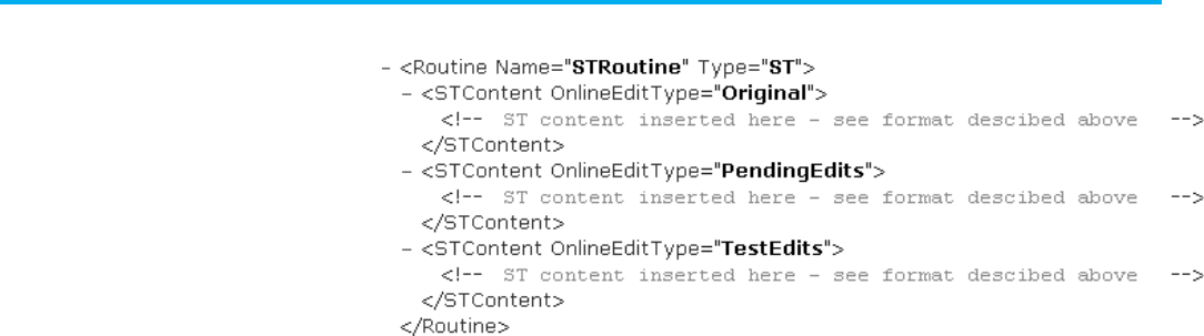
Chapter 12 Define a structured text routine
224 Publication 1756-RM014B-EN-P - November 2023
L5X example: test edits and pending edits exist
L5K Example 1: Test edits and pending edits exist
ST_ROUTINE MySTRoutine
LOGIC (Online_Edit_Type := Orig)
(* structured text logic here *)
END_LOGIC
LOGIC (Online_Edit_Type := Test)
(* structured text logic here *)
END_LOGIC
LOGIC (Online_Edit_Type := Pend)
(* structured text logix here *)
END_LOGIC
END_ST_ROUTINE
L5K Example 2: Only pending edits exist
ST_ROUTINE MySTRoutine
LOGIC (Online_Edit_Type := Orig)
(* structured text logic here *)
END_LOGIC
LOGIC (Online_Edit_Type := Pend)
(* structured text logic here *)
END_LOGIC
END_ST_ROUTINE
L5X structured text routine example
Structured text routine
examples
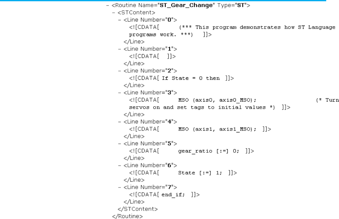
Chapter 12 Define a structured text routine
Publication 1756-RM014B-EN-P - November 2023 225
L5K structured text ST_ROUTINE example
This is an example of an exported structured text routine.
ST_ROUTINE <routine_name>
(*----------- Sample of ST
code-----------------------------*)
‘IF (myInteger = 12) THEN
‘ myInteger := ((5 * myInputInteger1) + (7 *
myInteger2)) - 71;
‘ WHILE (myTmpVar >= 0) DO
‘ myInteger := myInteger + 3;
‘ myTmpVar := myTmpVar - 1;
‘ END_WHILE;
‘END_IF;
ND_ST_ROUTINE
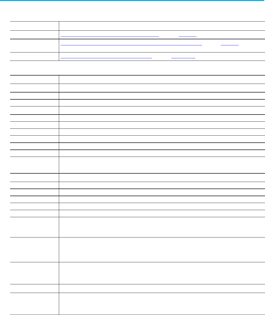
Chapter 12 Define a structured text routine
226 Publication 1756-RM014B-EN-P - November 2023
These tables list each structured text instruction and function. For more
details, see these reference manuals.
Instruction Type
Resource
Basic, sequential instruction Logix5000 Controllers General Instructions Set Reference Manual, publication 1756-RM003
.
Process control or drives
instruction
Logix5000 Controllers Advanced Process Control and Drives Instruction Set Reference Manual
,
publication1756-RM006
.
Motion instruction
Logix5000 Controllers Motion Instructions Reference Manual, publication MOTION-RM002.
Structured Text Instructions
Instruction
Neutral Text Format
ABL ABL(
Channel,SerialPortControl
);
ABS dest := ABS(
source
);
ACB
ACB(
Channel,SerialPortControl
);
ACL ACL(
Channel,ClearSerialPortRead,ClearSerialPortWrite
);
ACOS
dest
:= ACOS(
source
);
ADD
dest := sourceA + sourceB
;
AHL
AHL(
Channel,ANDMask,ORMask,SerialPortControl
);
ALM
ALM(
ALM_tag
);
ALMA
ALMA (
ALMA_tag
,
In
,
ProgAckAll
,
ProgramDisable
,
ProgEnable
);
ALMD ALMD (
ALMD_tag
,I
n
,
ProgAck,ProgReset
,
ProgDisable
,
ProgEnable
);
AND
dest := sourceA & sourceB
;
dest := sourceA
AND
sourceB
;
ARD ARD(
Channel,Destination,SerialPortControl
);
ARL
ARL(
Channel,Destination,SerialPortControl
);
ASIN
dest
:= ASIN(
source
);
ATAN
dest
:= ATAN(
source
);
AWA
AWA(
Channel,Source,SerialPortControl
);
AWT
AWT(
Channel,Source,SerialPortControl
);
BAND
IF
operandA
AND
operandB
THEN
<
statement
>;
ENDIF;
BNOT IF NOT
operand
THEN
<
statements
>;
ENDIF;
BOR
IF
operandA
OR
operandB
THEN
<
statements
>;
ENDIF;
BTDT BTD(
BTDT_tag
);
BXOR IF
operandA
XOR
operandB
THEN
<
statements
>;
ENDIF;
Structured text

Chapter 12 Define a structured text routine
Publication 1756-RM014B-EN-P - November 2023 227
Instruction
Neutral Text Format
CASE...OF
CASE
numeric_expression
OF
selector1: statement;
selectorN: statement;
ELSE
statement;
END_CASE;
CLR
dest
:= 0;
CONCAT
CONCAT(
SourceA,SourceB,Dest
)
COP
COP(
Source,Dest,Length
);
COS
dest
:= COS(
source
);
CPS CPS(
Source,Dest,Length
)
CTUD CTUD(
CTUD_tag
);
D2SD
D2SD(
D2SD_tag
);
D3SD
D3SD(
D3SD_tag
);
DEDT
DEDT(
DEDT_tag,storage
);
DEG
dest
:= DEG(
source
);
DELETE
DELETE(
Source,Qty,Start,Dest
);
DERV
DERV(
DERV_tag
);
DFF
DFF(
DFF_tag
);
DIV
dest :=
sourceA / sourceB
;
DTOS
DTOS(
Source,Dest
);
EOT EOT(
DataBit
);
EQU IF
sourceA
= source
B
THEN
<
statements
>;
ENDIF;
ESEL ESEL(
ESEL_tag
);
EVENT
EVENT(
task
);
FGEN
FGEN(
FGEN_tag,X1,Y1,X2,Y2
);
FIND
FIND(
Source,Search,Start,Result
)
FOR...DO
FOR
count
:=
initial_value
TO
final_value
BY
increment
DO
<statement>;
END_FOR;
GEQ IF
sourceA
>= source
B
THEN
<
statements
>;
ENDIF;
GRT IF
sourceA
> source
B
THEN
<
statements
>;
ENDIF;
GSV GSV(
ClassName,InstanceName,AttributeName,Dest
);
HLL
HLL(
HLL_tag
);
HPF
HPF(
HPF_tag
);
IF...THEN IF
bool_expression
THEN
<statement>
;
END_IF;
INSERT
INSERT(
SourceA,SourceB,Start,Dest
);
INTG
INTG(
INTG_tag
);

Chapter 12 Define a structured text routine
228 Publication 1756-RM014B-EN-P - November 2023
Instruction
Neutral Text Format
IOT
IOT(
output_tag
);
JKFF JKFF(
JKFF_tag
);
JSR
JSR(
RoutineName,InputCount,InputPar,ReturnPar
);
LDL2
LDL2(
LDL2_tag
);
LDLG
LDLG(
LDLG_tag
);
LEQ IF
sourceA
<= source
B
THEN
<
statements
>;
ENDIF;
LES IF
sourceA
< source
B
THEN
<
statements
>;
ENDIF;
LN
dest
:= LN(
source
);
LOG
dest
:= LOG(
source
);
LOWER
LOWER(
Source,Dest);
LPF LPF(
LPF_tag
);
MAAT MAAT(
Axis,MotionControl
);
MAFR
MAFR(
Axis,MotionControl
);
MAG MAG(SlaveA
xis,MasterAxis,MotionControl,Direction,Ratio,SlaveCounts,
MasterCounts,MasterReference,RatioFormat,Clutch,AccelRate,AccelUnits
);
MAH MAH(
Axis,MotionControl
);
MAHD
MAHD(
Axis,MotionControl,DiagnosticTest,ObservedDirection
);
MAJ MAJ(
Axis,MotionControl,Direction,Speed,SpeedUnits,AccelRate,AccelUnits,
DecelRate,DecelUnits,Profile,Merge,MergeSpeed
);
MAM MAM(
Axis,MotionControl,MoveType,Position,Speed,SpeedUnits,AccelRate,
AccelUnits,DecelRate,DecelUnits,Profile,Merge,MergeSpeed
);
MAOC MAOC(
Axis,ExecutionTarget,MotionControl,Output,Input,OutputCam,
CamStartPosition,CamEndPosition,OutputCompensation,ExecutionMode,
ExecutionSchedule,AxisArmPosition,CamArmPosition,Reference
);
MAPC MAPC(
SlaveAxis
,
MasterAxis
,M
otionControl
,D
irection
,C
amProfile
,
SlaveScaling
,M
asterScaling
,E
xecutionMode
,
ExecutionSchedule
,
MasterLockPosition
,
CamLockPosition
,
MasterReference
,
MasterDirection
);
MAR MAR(
Axis,MotionControl,TriggerCondition,WindowedRegistration,
MinimumPosition,MaximumPosition
);
MAS MAS(
Axis,MotionControl,StopType,ChangeDecel,DecelRate,DecelUnits
);
MASD
MASD(
Axis,MotionControl
);
MASR
MASR(
Axis,MotionControl
);
MATC MATC(
Axis
,
MotionControl
,
Direction
,
CamProfile
,
DistanceScaling
,
TimeScaling
,
ExecutionMode
,
ExecutionSchedule
);
MAVE MAVE(
MAVE_tag,storage,weight
);
MAW
MAW(
Axis,MotionControl,TriggerCondition,Position
);
MAXC
MAXC(
MAXC_tag
);
MCCD MCCD(
Coordinate_system,MotionControl,MotionType,ChangeSpeed,Speed,
SpeedUnits,ChangeAccel,AccelRate,AccelUnits,ChangeDecel,DecelRate,
DecelUnits,Scope
);
MCCM
MCCM(
CoordinateSystem,MotionControl,MoveType,Position,CircleType,
Via/Center/Radius,Direction,Speed,SpeedUnits,AccelRate,AccelUnits,
DecelRate,DecelUnits,Profile,TerminationType,Merge,MergeSpeed
);
MCCP MCCP(
MotionControl
,
Cam
,
Length
,
StartSlope
,
EndSlope
,
CamProfile
);

Chapter 12 Define a structured text routine
Publication 1756-RM014B-EN-P - November 2023 229
Instruction
Neutral Text Format
MCD
MCD(A
xis,MotionControl,MotionType,ChangeSpeed,Speed,ChangeAccel,
AccelRate,ChangeDecel,DecelRate,SpeedUnits,AccelUnits,DecelUnits
);
MCLM MCLM(
CoordinateSystem,MotionControl,MoveType,Position,Speed,SpeedUnits,
AccelRate,AccelUnits,DecelRate,DecelUnits,Profile,TerminationType,Merge,
MergeSpeed
);
MCS MCS(
CoordinateSystem
,
MotionControl
,
StopType
,
ChangeDecel
,
DecelRate
,
DecelUnits
);
MCSD MCSD(
CoordinateSystem,MotionControl
);
MCSR MCSR(
CoordinateSystem,MotionControl
);
MCSV
MCSV(
MotionControl,CamProfile,MasterValue,SlaveValue,SlopeValue,
SlopeDerivative
);
MCT MCT(
SourceSystem,TargetSystem,MotionControl,Orientation,Translation
);
MCTP MCTP(
SourceSystem,TargetSystem,MotionControl,Orientation,Translation,
TransformDirection
,
ReferencePosition
,
TransformPosition
);
MDF MDF(
Axis,MotionControl
);
MDO
MDO(
Axis,MotionControl,DriveOutput,DriveUnits
);
MDOC
MDOC(
Axis,ExecutionTarget,MotionControl,DisarmType
);
MDR
MDR(
Axis,MotionControl
);
MDW
MDW(
Axis,MotionControl
);
MEQ IF (Source AND Mask) = (Compare AND Mask) THEN
<statements
>;
END_IF;
MGS MGS(
Group,MotionControl,StopMode
);
MGSD MGSD(
Group,MotionControl
);
MGSP MGSP(
Group,MotionControl
);
MGSR
MGSR(
Group,MotionControl
);
MID
MID(
Source,Qty,Start,Dest
);
MINC MINC(
MINC_tag
);
MOD
dest
:=
sourceA
MOD
sourceB
;
MRAT
MRAT(
Axis,MotionControl
);
MRHD
MRHD(
Axis,MotionControl,DiagnosticTest
);
MRP
MRP(A
xis,MotionControl,Type,PositionSelect,Position
);
MSF
MSF(
Axis,MotionControl
);
MSG MSG(
MessageControl
);
MSO MSO(
Axis,MotionControl
);
MUL
dest
:=
sourceA
*
sourceB
;
MVMT
MVMT(
MVMT_tag
);
NEG
dest
:= -
source
;
NEQ IF
sourceA
<>
sourceB
THEN
<
statements
>;
END_IF;
NOT IF NOT
source
THEN
<
statements
>;
END_IF;
OR
dest
:=
sourceA
OR
sourceB
OSFI
OSFI(
OSFI_tag
);
OSRI
OSRI(
OSRI_tag
);
OTE
data_bit
[:=]
BOOL_expression
;

Chapter 12 Define a structured text routine
230 Publication 1756-RM014B-EN-P - November 2023
Instruction
Neutral Text Format
OTL
IF
BOOL_expression
THEN
data_bit
:= 1;
END_IF;
OTU IF
BOOL_expression
THEN
data_bit
:= 0;
END_IF;
PATT PATT(P
haseName,Result
);
PCLF PCLF(
PhaseName
);
PCMD
PCMD(
PhaseName,Command,Result
);
PDET
PDET(
PhaseName
);
PFL
PFL(
Source
);
PI
PI(
PI_tag
);
PID PID(PID
,ProcessVariable,Tieback,ControlVariable,PIDMasterLoop,InholdBit,
InholdValue);
PIDE PIDE(
PIDE_tag
);
PMUL
PMUL(
PMUL_tag
);
POSP
POSP(
POSP_tag
);
POVR POVR(
PhaseName,Command,Result);
PPD
PPD();
PRNP
PRNP();
PSC
PSC();
PXRQ
PXRQ(
PhaseInstruction,ExternalRequest,DataValue
);
RAD
dest
:= RAD(
source
);
REPEAT...UNTIL REPEAT
<statement>;
UNTIL bool_expression
END_REPEAT;
RESD RESD(
RESD_tag
);
RET
RET(
ReturnPar)
;
RLIM
RLIM(
RLIM_tag
);
RMPS
RMPS(
RMPS_tag,RampValue,SoakValue,SoakTime
);
RTOR
RTOR(
RTOR_tag
);
RTOS RTOS(
Source,Dest
)
SBR SBR(
InputPar
);
SCRV
SCRV(
SCRV_tag
);
SETD
SETD(
SETD_tag
);
SFP SFP(SFCRoutineName,TargetState);
SFR
SFR(SFCRoutineName,StepName);
SIN
dest := SIN(
source
);
SIZE
SIZE(
Souce,Dimensiontovary,Size
);
SNEG
SNEG(
SNEG_tag
);
SOC
SOC(
SOC_tag
);
SQRT
dest
:= SQRT(
source
);
SRT SRT(
Array,Dimtovary,Control
);
SRTP
SRTP(
SRTP_tag
);
SSUM
SSUM(
SSUM_tag
);
SSV
SSV(
ClassName,InstanceName,AttributeName,Source
);
Chapter 12 Define a structured text routine
Publication 1756-RM014B-EN-P - November 2023 231
Instruction
Neutral Text Format
STOD
STOD(
Source,Dest
)
STOR STOR(
Source,Dest
)
SUB
dest
:=
sourceA - sourceB
;
SWPB SWPB(
Source,OrderMode,Dest
);
TAN
dest
:= TAN(
source
);
TOFR
TOFR(
TOFR_tag
);
TONR
TONR(
TONR_tag
);
TOT
TOT(
TOT_tag
);
TRUNC
dest
:= TRUNC(
source
);
UID
UID();
UIE
UIE();
UPDN
UPDN(
UPDN_tag
);
UPPER
UPPER(
Source,Destination);
WHILE...DO WHILE
bool_expression
DO
<statement>;
END_WHILE;
XIC IF
data_bit
THEN
<
statement
>;
END_IF;
XIO IF NOT
data_bit
THEN
<
statement
>;
END_IF;
XOR
dest
:=
sourceA
XOR
sourceB
;
XPY
dest
:=
sourceX
XPY
sourceY
;

Publication 1756-RM014B-EN-P - November 2023 233
Chapter 13
Define an Equipment Sequence routine
This chapter explains how to define an Equipment Sequence routine in a
complete import/export file.
The following examples show Equipment Sequence structure.
<Routines>
<Routine [Routine_Attributes]>
<Description>
<![CDATA[ text ]]>
</Description>
<SEQContent [SEQContent_Attributes]>
<Step [Step_Attributes]/>
<Transition [Transition_Attributes]/>
<Branch [Branch_Attributes]/>
<Stop [Stop_Attributes]/>
<DirectedLink
[DirectedLink_Attributes]/>
<TextBox [TextBox_Attributes]>
text
</TextBox>
<Attachment [Attachment_Attributes]/>
<TagConfigurations>
[TagConfiguration]
</TagConfigurations/>
</SEQContent>
</Routine>
</Routines>
Equipment Sequence
routine introduction
Equipment Sequence
Routine
L5X Equipment Sequence
structure
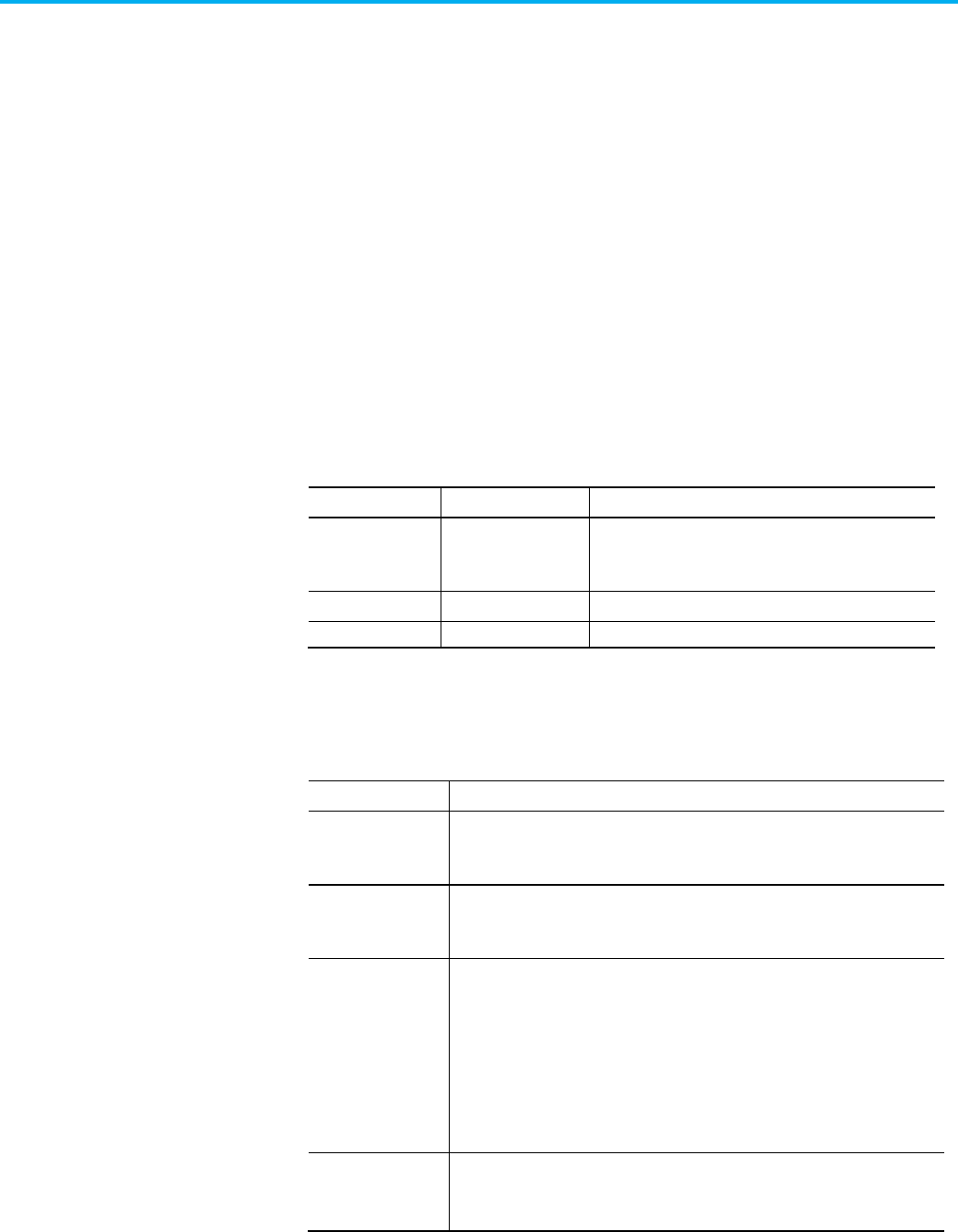
Chapter 13 Define an Equipment Sequence routine
234 Publication 1756-RM014B-EN-P - November 2023
ESQ_ROUTINE <routine_name> [(Routine_Attributes,
SFC_Attributes)]
<STEP declaration>
<TRANSITION declaration>
<BRANCH declaration>
<STOP declaration>
<DIRECTED_LINK declaration>
<TEXT_BOX declaration)
<ATTACHMENT declaration>
<TAG_CONFIGURATION declaration>
END_ESQ_ROUTINE
See the table for Equipment Sequence elements for .L5X and .L5K items and
identifiers.
L5X Item
L5K Item
Identifies
N/A routine_name The name of the routine.
In L5X, use a Name attribute on the <Routine> element.
Description Description User information about the routine.
SEQContent
N/A
Equipment sequence logic.
This table contains ESQ routine attributes and descriptions.
Attribute
Description
Name L5X only. Specify the name of the routine.
For L5K, the name is an element of the statement.
Type L5X only. Specify "Sequence".
In L5K, the type of routine is part of the routine statement.
SheetSize
The size of the Equipment Sequence. Select one of these options.
• Letter (8.5x11in)
• Legal (8.5x14in)
• Tabloid (11x17in)
• A4 (210x297mm)
• A3 (297x420mm)
In L5X, this attribute is on the <SEQContent> element.
SheetOrientation
The orientation of the Equipment Sequence sheet. Select Portrait or Landscape.
In L5X, this attribute is on the <SEQContent> element.
L5K Equipment Sequence
ESQ_ROUTINE structure
Equipment Sequence
elements
ESQ_Routine attributes
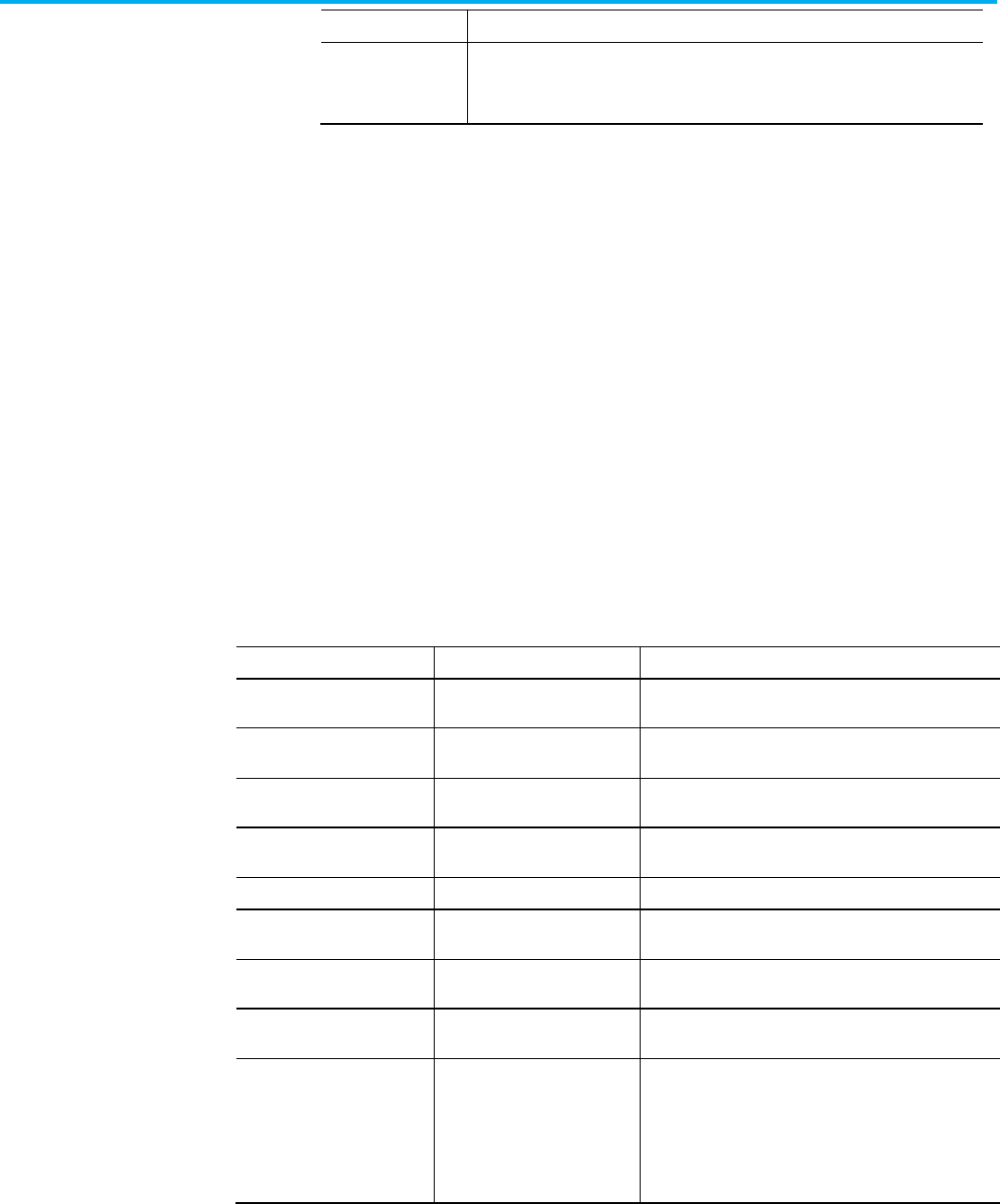
Chapter 13 Define an Equipment Sequence routine
Publication 1756-RM014B-EN-P - November 2023 235
Attribute
Description
PermissionSet
Name of the set of permissions, configured in FactoryTalk Security, to apply to this
object.
These examples show the step structure.
<Step [Step_Attributes] />
Refer to the L5K STEP structure.
STEP (Step_Attributes)
END_STEP
L5X Item
L5K Item
Identifies
ID ID The step identifier. This ID uniquely identifies this step from
all other blocks. Type an unsigned, 32-bit integer value.
X
X
X-coordinate on internal grid. Type an unsigned, 32-bit
integer value.
Y Y Y-coordinate on internal grid. Type an unsigned, 32-bit
integer value.
Operand Operand The step tag. Type a tag of datatype ESQ_STEP. The import
process uses this tag name to name the step.
HideDesc
HideDescription
Whether or not to hide the step description. Type Yes or No.
DescX DescriptionX X-coordinate on internal grid of the description box. Type an
unsigned, 32-bit integer value.
DescY
DescriptionY
Y-coordinate on internal grid of the description box. Type
unsigned, 32-bit integer value.
DescWidth DescriptionWidth This attribute is not currently used; it is there for future use.
Type
0
.
InitialStep InitialStep Whether this step is the initial step of the routine. Type
Yes
or
No
.
If you have multiple steps identified as the initial step, which
is incorrect syntax, the import process designates the last
initial step it encounters as the initial step and removes the
initial step indicators from any other steps.
Steps
Structured text L5X step
structure
Structured text L5K STEP
structure
Structured text step
attributes
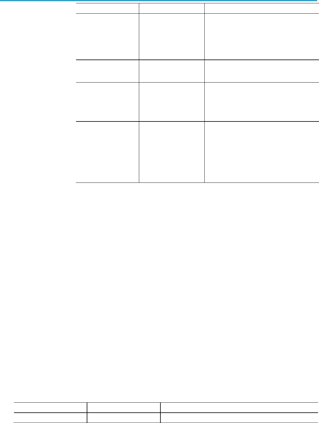
Chapter 13 Define an Equipment Sequence routine
236 Publication 1756-RM014B-EN-P - November 2023
L5X Item
L5K Item
Identifies
NoPhaseStep
NoPhaseStep
Whether this step is a place holder step, a step which is
configured not to
start any equipment phase. PhaseName
attributes are ignored if NoPhaseStep is set to
Yes
in L5K,
true
in L5X.
L5K: Yes/No, L5X: true/false.
PhaseName PhaseName The name of the Phase associated with the step. Can be an
empty string.
TransferOfControlSource TransferOfControlSource Specifies whether this step will transfer control of its
equipment phase to an immediately following step without
stopping and resetting the phase.
L5K:
Yes
/
No
, L5X:
true
/
false
.
TransferOfControlTarget TransferOfControlTarget Specifies whether this step will accept the transfer control
of its equipment phase from an immediately preceding step
without starting the phase. The phase logic is expected to be
executing a state routine. The executing routine is notified
of the transfer of control and can request new input
parameters, if programmed to do so, from the target step.
L5K: Yes/No, L5X: true/false.
These examples show transition structure.
Refer to the L5X transition structure.
<Transition [Transition_Attributes]>
<Condition>
logic
</Condition>
</Transition>
Refer to the L5K TRANSITION structure.
TRANSITION (Transition_Attributes)
<CONDITION declaration>
END_TRANSITION
Refer to the L5X and L5K transition element and identifier.
L5X Item
L5K Item
Identifies
Condition CONDITION The condition to evaluate for the transition.
Transitions
L5X transition structure
L5K TRANSITION structure
Transition elements
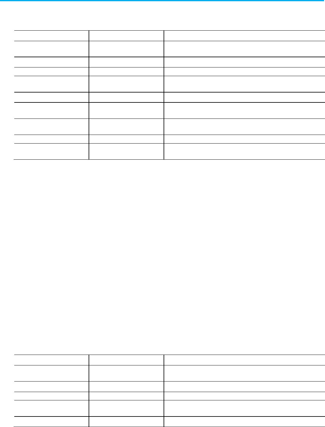
Chapter 13 Define an Equipment Sequence routine
Publication 1756-RM014B-EN-P - November 2023 237
Refer to the L5X and L5K transition attributes and identifiers.
L5X Item
L5K Item
Identifies
ID
ID
The step identifier. This ID uniquely identifies this step from all other blocks. Type
an unsigned, 32-bit integer value.
X X X-coordinate on internal grid. Type an unsigned, 32-bit integer value.
Y
Y
Y-coordinate on internal grid. Type an unsigned, 32-bit integer value.
Operand Operand The step tag. Type a tag of datatype SFC_STEP. The import process uses this tag
name to name the step.
HideDesc HideDescription Whether or not to hide the step description. Type
Yes
or
No
.
DescX DescriptionX X-coordinate on internal grid of the description box. Type an unsigned,
32-bit integer value.
DescY DescriptionY Y-coordinate on internal grid of the description box. Type unsigned, 32-bit integer
value.
DescWidth
DescriptionWidth
This attribute is not currently used; it is there for future use. Type 0.
Force Force The transition is forced. Type
true
for forced true (set) or type
false
for forced false
(cleared). If the transition is not forced, do not enter this attribute.
These examples show stop structure.
Refer to the L5X stop structure.
<Stop [StopAttributes]/>
Refer to the L5K STOP structure.
STOP (Stop_Attributes)
END_STOP
Refer to the L5X and L5K stop attributes and identifiers.
L5X Item
L5K Item
Identifies
ID
ID
The stop identifier. This ID uniquely identifies this stop from all other blocks. Type
an unsigned, 32-bit integer value.
X X X-coordinate on internal grid. Type an unsigned, 32-bit integer value.
Y
Y
Y-coordinate on internal grid. Type an unsigned, 32-bit integer value.
Operand Operand The stop tag. Type a tag of datatype SFC_STOP. The import process uses this tag
name to name the stop.
HideDesc HideDescription Whether or not to hide the stop description. Type
Yes
or
No
.
Transition attributes
Stops
L5X stop structure
L5K STOP structure
Stop attributes
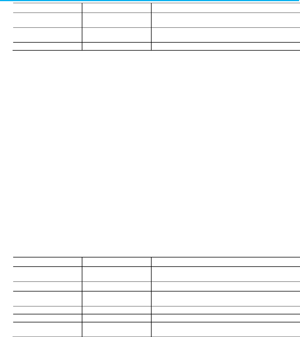
Chapter 13 Define an Equipment Sequence routine
238 Publication 1756-RM014B-EN-P - November 2023
L5X Item
L5K Item
Identifies
DescX
DescriptionX
X-coordinate on internal grid of the description box. Type an unsigned,
32-bit integer value.
DescY
DescriptionY
Y-coordinate on internal grid of the description box. Type unsigned, 32-bit integer
value.
DescWidth DescriptionWidth This attribute is not currently used; it is there for future use. Type
0
.
The branch blocks in an Equipment Sequence routine identify simultaneous
or selection branches in the routine.
Refer to the L5X branch structure.
<Branch [BranchAttributes]>
<Leg [LegAttributes]/>
</Branch>
Refer to the L5K BRANCH structure.
BRANCH (Branch_Attributes)
LEG (Leg_Attributes)
END_LEG
END_BRANCH
See the table for .L5X and .L5K items and identifiers.
L5X Item
L5K Item
Identifies
ID ID The branch identifier. This ID uniquely identifies this branch from all other blocks.
Type an unsigned, 32-bit integer value.
X X X-coordinate on internal grid. Type an unsigned, 32-bit integer value.
Y Y Y-coordinate on internal grid. Type an unsigned, 32-bit integer value.
BranchType
BranchType
The type of branch. Type Simultaneous or Selection.
BranchFlow BranchFlow The direction of the branch. Type
Converge
or
Diverge
.
Priority Priority Whether the priority of a divergent selection branch is defined by the user. This
attribute applies only to divergent selection branches. Type Default or UserDefined.
Equipment Sequence
routine branches
L5X branch structure
L5K BRANCH structure
Branch attributes
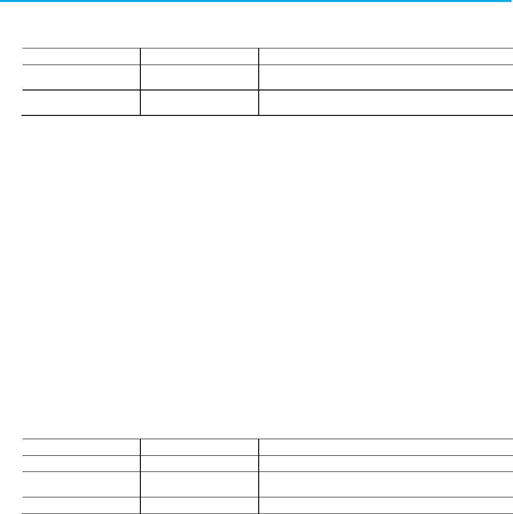
Chapter 13 Define an Equipment Sequence routine
Publication 1756-RM014B-EN-P - November 2023 239
Refer to the L5X and L5K let attributes and identifiers.
L5X Item
L5K Item
Identifies
ID
ID
The leg identifier. This ID uniquely identifies this leg from all other blocks. Type an
unsigned, 32-bit integer value.
Force Force Whether the leg is forced or not. You can force only a leg in a simultaneous branch.
Omit this attribute, for no forces, or type
false
to force the leg false.
The directed link blocks in an Equipment Sequence routine identify the links
between Equipment Sequence components.
Refer to the L5X DirectedLink structure.
<DirectedLink [DirectedLinkAttributes]/>
Refer to the L5K DIRECTED_LINK structure.
DIRECTED_LINK (Directed_Link_Attributes)
END_DIRECTED_LINK
See the table for direct link attributes .L5X and .L5K items and identifiers.
L5X Item
L5K Item
Identifies
FromID FromElementID The ID of the object. Type an unsigned, 32-bit integer value.
ToID ToElementID The ID of the object that the FromID object is attached to. Type an unsigned, 32-bit
integer value.
Show ShowLink Whether or not to show the link. Type
TRUE
or
FALSE
.
Use these guidelines for directed links:
• All directed link blocks must come after all step, transition, stop, and
branch blocks.
• A directed link links only one element to one other element.
Leg attributes
Equipment Sequence
directed links
L5X DirectedLink structure
L5K DIRECTED_LINK
structure
Directed link attributes
Directed link guidelines
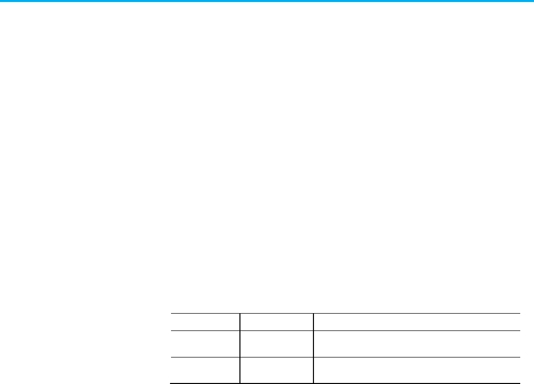
Chapter 13 Define an Equipment Sequence routine
240 Publication 1756-RM014B-EN-P - November 2023
The attachment blocks in an Equipment Sequence routine identify the
attachments from text boxes to other Equipment Sequence elements.
Refer to the L5X attachment structure.
<Attachment [Attachment_Attributes]/>
Refer to the L5K ATTACHMENT structure.
ATTACHMENT (Attachment_Attributes)
END_ATTACHMENT
See the table for .L5X and .L5K items and identifiers.
L5X Item
L5K Item
Identifies
FromID
FromElementID
The ID of the attached object. Type an unsigned, 32-bit integer
value.
ToID
ToElementID
The ID of the object that the FromID object is attached to. Type
an unsigned, 32-bit integer value.
Use these guidelines for attachments:
• Use an attachment to link a text box to an Equipment Sequence
element.
• All attachment blocks must come after all text box blocks.
The following examples show the tag configuration structure.
Refer to the L5X tag configuration structure.
<TagConfigurations>
<TagConfiguration [Tag_Configuration_Attributes]>
<Expression>
logic
Equipment Sequence
attachments
L5X attachment structure
L5K ATTACHMENT structure
Attachment attributes
Equipment Sequence
element attachment
guidelines
Tag configuration
L5X tag configuration
structure

Chapter 13 Define an Equipment Sequence routine
Publication 1756-RM014B-EN-P - November 2023 241
</Expression>
</TagConfiguration>
</TagConfigurations>
TAG_CONFIGURATION (Step_Attributes)
<EXPRESSION declaration>
END_TAG_CONFIGURATION
L5X Item
L5K Item
Description
Expression EXPRESSION The expression to evaluate for the tag.
The expression component uses a structured text expression to specify an
expression to evaluate for the sequence tag.
<Expression>
<STContent>
<Line Number="0">
<![CDATA[ structured_text; ]]>
</Line>
</STContent>
</Expression>
Refer to the L5K EXPRESSION structure.
EXPRESSION (LanguageType := ST)
‘<structured_text>
END_EXPRESSION
Tip: Each line of L5K structured text begins with a single quote (‘).
L5K TAG_CONFIGURATION
structure
Tag configuration elements
Expression component
L5X expression structure
L5K EXPRESSION structure
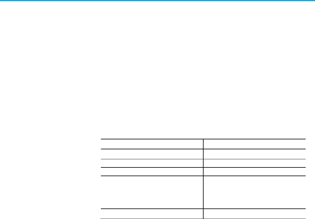
Publication 1756-RM014B-EN-P - November 2023 243
Chapter 14
Define a task component
This chapter explains the overall structure of the task component.
A task component defines a task in the controller project. The maximum
number of tasks depends on the type of controller.
Controller
Maximum Number of Tasks
ControlLogix 32
SoftLogix5800 32
FlexLogix 8
CompactLogix
• 1768-L30x
• 1769-L33x
• 1769-L36x
32
32
23
DriveLogix 8
Refer to the L5K TASK structure.
TASK <task_name> [(Description := "text", Attributes)]
<program_name>;
END_TASK
Refer to the L5X task structure.
<Tasks>
<Task [Task_Attributes]>
<Description>
<![CDATA[ text ]]>
</Description>
<EventInfo [EventInfo_Attributes]>
<ScheduledPrograms>
< ScheduledProgram Name="program_name" />
Task component
introduction
Task component
L5K TASK structure
L5X task structure
Chapter 14 Define a task component
244 Publication 1756-RM014B-EN-P - November 2023
</Programs>
</Task>
</Tasks>
Refer to the L5X and L5K task elements and descriptions.
L5X Item
L5K Item
Description
N/A
task_name
The name of the task.
In L5X, use a Name attribute on the <Task> element.
Description Description User information about the task.
EventInfo N/A Event information for an event task
ScheduledProgram
program_name
Each program within the task.
Refer to the task attributes and descriptions.
Attribute
Description
Name L5X only. Specify the name of the task.
In L5K, the name is an element of the statement.
Type Specify whether the type of task is
Continuous
,
Periodic
, or
Event
. There can be only one continuous task.
Class Specify the class of the task. This attribute applies only to safety controller projects. Type
Standard
or
Safety
.
Rate
If the task is a periodic task, specify how often to run the task (1.000...2,000,000.000 µs).
Priority Specify the priority of a periodic task (1...15)
Watchdog
Type the watchdog timeout for the task (1.000...2,000,000.000 µs).
EventTrigger Only used for event tasks.
Specify the trigger for the event task. Type
Axis Home
,
Axis Watch
,
Axis Registration 1
,
Axis Registration 2
,
Motion Group Execution
,
EVENT Instruction Only
,
Module Input Data State Change
,
Consumed Tag
, or
Windows Event
.
In L5X, this attribute is on the <EventInfo> element.
EventTag Only used for event tasks with a Consumed Tag trigger or a Module Input Data State Change trigger.
Specify the tag to consume.
In L5X, this attribute is on the <EventInfo> element.
EnableTimeout Type
Yes
to enable timeouts for the task. Otherwise type
No
.
In L5X, this attribute is on the <EventInfo> element.
DisableUpdateOutputs Type
Yes
to disable updates to outputs while the task executes. Otherwise type
No
. The default for a periodic
or continuous task is No. The default for an event task is
yes
.
InihibitTask
Type Yes to inhibit the task. Otherwise enter No.
Observe these guidelines when defining a task:
• Tasks must be defined after programs and before controller objects.
• There is a maximum of 32 tasks.
• There is one continuous task only.
Task elements
Task attributes
Task guidelines
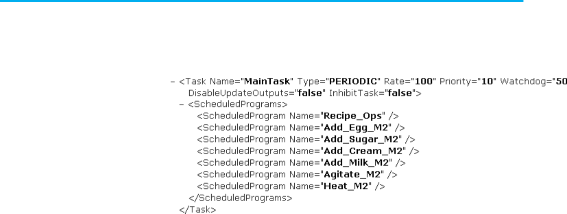
Chapter 14 Define a task component
Publication 1756-RM014B-EN-P - November 2023 245
• A program can be scheduled under one task only.
• Scheduled programs must be defined (must exist).
L5X Task example
L5K TASK example
TASK joe (Type := Periodic, Priority := 8, Rate := 10000)
sue;
betty;
END_TASK
You can define the task attributes (Type, Priority, Rate, and Watchdog) in any
order. The list of programs scheduled for a task are listed in the task
declarations block, as shown above. The programs are executed in the order
they are specified.
L5K Safety TASK Example
TASK SafetyTask (Type := PERIODIC,
Class := Safety,
Rate := 10,
Priority := 10,
Watchdog := 10,
DisableUpdateOutputs := No,
InhibitTask := No)
SafetyProgram;
END_TASK
Task component examples

Publication 1756-RM014B-EN-P - November 2023 247
Chapter 15
Define a parameter connection component
This chapter explains the overall structure of the parameter connection
component.
A parameter connection component defines a connection between two
program parameters, which allows you to share data between programs
without using controller-scope tags.
Refer to the L5K PARAMETER_CONNECTION structure.
PARAMETER_CONNECTION
(EndPoint1:=<program.parameter_name>,
EndPoint2:=<program.parameter_name>)
END_PARAMETER_CONNECTION
Refer to the L5X ParameterConnection structure.
<ParameterConnections>
<ParameterConnection
EndPoint1="program_name.parameter_name",
EndPoint2="program_name.parameter_name" />
</ParameterConnections>
Refer to the parameter connection attributes and descriptions.
Attribute
Description
EndPoint1 Specify the first end point of the parameter connection.
EndPoint2 Specify the second end point of the parameter connection.
Parameter connection
component introduction
Parameter connection
component
L5K
PARAMETER_CONNECTION
structure
L5X ParameterConnection
structure
Parameter connection
attributes
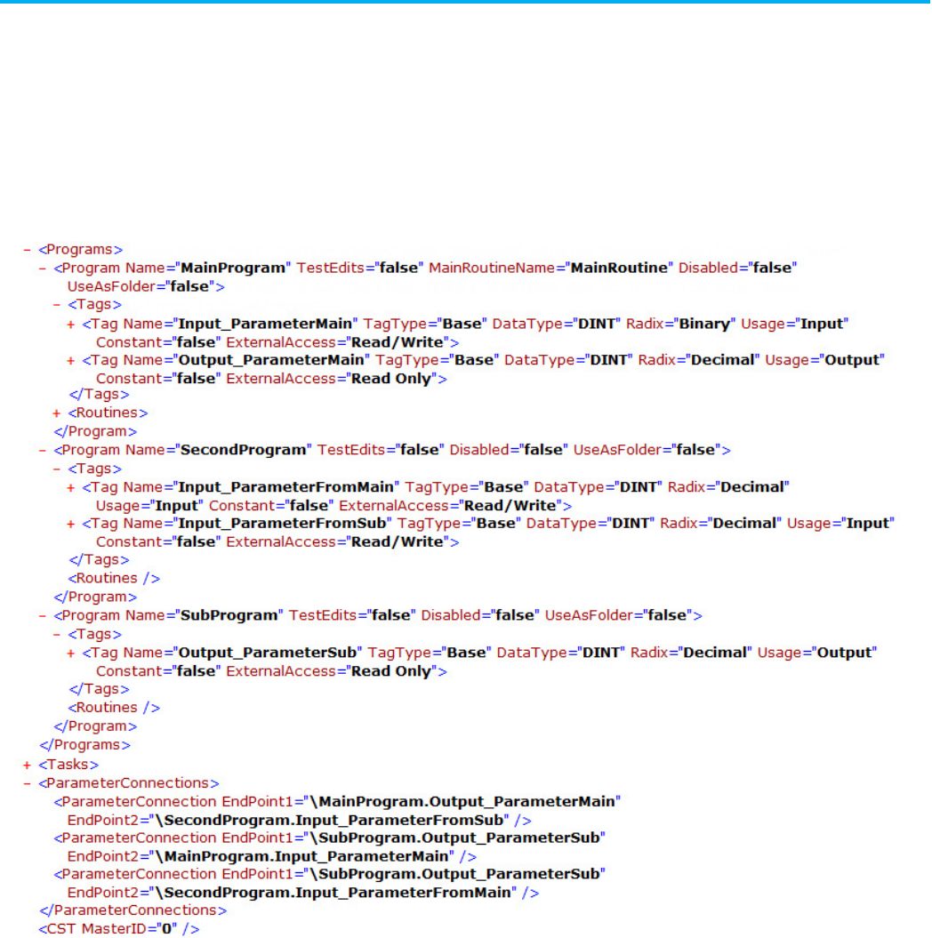
Chapter 15 Define a parameter connection component
248 Publication 1756-RM014B-EN-P - November 2023
Observe this guideline when defining a parameter connection:
• Parameter connections must be defined after tasks.
L5X ParameterConnection example
L5K PARAMETER_CONNECTION examples
PROGRAM MainProgram (MAIN := "MainRoutine",
MODE := 0,
DisableFlag := 0,
UseAsFolder := 0)
TAG
Input_ParameterMain : DINT (RADIX := Binary,
Usage := Input) := 0;
Output_ParameterMain : DINT (RADIX := Decimal,
Usage := Output,
Parameter connection
guidelines
Parameter connection
component examples

Chapter 15 Define a parameter connection component
Publication 1756-RM014B-EN-P - November 2023 249
ExternalAccess := Read Only) := 0;
Program_tag1 : DINT (RADIX := Decimal,
Constant := Yes,
ExternalAccess := Read Only) := 0;
END_TAG
ROUTINE MainRoutine
END_ROUTINE
CHILD_PROGRAMS
END_CHILD_PROGRAMS
END_PROGRAM
PROGRAM SecondProgram (MODE := 0,
DisableFlag := 0,
UseAsFolder := 0)
TAG
Input_ParameterFromMain : DINT (RADIX := Decimal,
Usage := Input) := 0;
Input_ParameterFromSub : DINT (RADIX := Decimal,
Usage := Input) := 0;
END_TAG
CHILD_PROGRAMS
END_CHILD_PROGRAMS
END_PROGRAM
PROGRAM SubProgram (MODE := 0,
DisableFlag := 0,
UseAsFolder := 0)
TAG
Output_ParameterSub : DINT (RADIX := Decimal,
Usage := Output,
ExternalAccess := Read Only) := 0;
END_TAG
CHILD_PROGRAMS
END_CHILD_PROGRAMS
END_PROGRAM
TASK MainTask (Type := CONTINUOUS,
Rate := 10,
Priority := 10,
Watchdog := 500,
DisableUpdateOutputs := No,
InhibitTask := No)
MainProgram;
SubProgram;
SecondProgram;
END_TASK
PARAMETER_CONNECTION (EndPoint1 :=
\MainProgram.Output_ParameterMain,

Chapter 15 Define a parameter connection component
250 Publication 1756-RM014B-EN-P - November 2023
EndPoint2 :=
\SecondProgram.Input_ParameterFromSub)
END_PARAMETER_CONNECTION
PARAMETER_CONNECTION (EndPoint1 :=
\SubProgram.Output_ParameterSub,
EndPoint2 :=
\MainProgram.Input_ParameterMain)
END_PARAMETER_CONNECTION
PARAMETER_CONNECTION (EndPoint1 :=
\SubProgram.Output_ParameterSub,
EndPoint2 :=
\SecondProgram.Input_ParameterFromMain)
END_PARAMETER_CONNECTION
CONFIG CST(SystemTimeMasterID := 0) END_CONFIG

Publication 1756-RM014B-EN-P - November 2023 251
Chapter 16
Define a trend component
This chapter explains the overall structure of the trend component.
A trend component defines a controller trend. Trend objects are optional. You
can have as many as 32 trends per import/export file.
Refer to the L5X trend structure.
<Trends>
<Trend [Trend_Attributes]>
<Description>
<![CDATA[ text ]]>
</Description>
<Template>
template_data
</Template>
<Pens>
pen
</Pens>
</Trend>
</Trends>
Refer to the L5K TREND structure.
TREND <trend_name> [(Description := "text",
Trend_Attributes)]
Template := [template_data];
[PEN declaration]
END_TREND
Trend component
introduction
Trend component
L5X trend structure
L5K TREND structure
Chapter 16 Define a trend component
252 Publication 1756-RM014B-EN-P - November 2023
Refer to the L5X and L5K trend elements and descriptions.
L5X Item
L5K Item
Description
N/A
trend_name
The name of the trend.
In L5X, use a Name attribute on the <Trend> element.
Description Description User information about the trend.
Template
template_data
The trend template in a byte value list.
Pens PEN Individual pens within the trend.
Each trend can support as many as 8 pens.
Refer to the trend attributes and descriptions.
Attribute
Description
Name L5X only. Specify the name of the trend.
In L5K, the name is an element of the statement.
SamplePeriod Specify how often trending tags are collected in msec (1 msec...30 minutes).
NumberOfCaptures
Specifies the maximum number of captures allowed (1...100).
CaptureSizeType
Define how the capture size is specified. Type Samples, TimePeriod, or NoLimit.
CaptureSize Specify the number of samples for each capture. The maximum number of samples is 2-hours worth of data
samples or 1000 samples, whichever is greater. If the CaptureSizeType is Samples, the range is 1...(2
hours/SamplePeriod) or 1000 samples, whichever is greater. If the CaptureSizeType is TimePeriod, the range is
SamplePeriod...2 hours or (SamplePeriod * 1000), whichever is greater.
StartTriggerType Specify the type of the start trigger. Type
NoTrigger
or
EventTrigger
.
StartTriggerTag1
Specify the tag name of the first start trigger. The name must be one of the pen names.
StartTriggerOperation1 Specify the operation that is applied on StartTriggerTag1, and StartTriggerTargetValue1 or
StartTriggerTargetTag1.
Enter: For:
0 Exact Equal (Tag EQU Target)
1 Trigger Level Equal (Tag = Target)
2 Not Equal (Tag != Target)
3 Less Than (Tag < Target)
4 Greater Than (Tag > Target)
5 Less Than or Equal To (Tag <= Target)
6 Greater Than or Equal To (Tag >= Target)
7 Positive Slope (slope of Tag is positive)
8 Negative Slope (slope of Tag is negative)
9 Bitwise OR ((Tag OR Target) = 0)
10 Bitwise OR ((Tag OR Target) != 0)
11 Bitwise AND ((Tag AND Target) = 0)
12 Bitwise AND ((Tag AND Target) != 0)
13 Bitwise XOR ((Tag XOR Target) = 0)
14 Bitwise XOR ((Tag XOR Target) != 0)
StartTriggerTargetType1 Specify the type of the first start trigger target. Type
TargetValue
or
TargetTag
. If you type
TargetValue
,
StartTriggerTargetValue1 is expected. Otherwise, StartTriggerTargetTag1 is expected.
StartTriggerTargetValue1 Specify a target value if the StartTriggerTargetType1 is
TargetValue
. Type a binary, octal, decimal, or
hexadecimal integer number or type a floating point number.
StartTriggerTargetTag1 Specify a target tag if the StartTriggerTargetType is
TargetTag
. The tag must be one of the pen names.
Trend elements
Trend attributes

Chapter 16 Define a trend component
Publication 1756-RM014B-EN-P - November 2023 253
Attribute
Description
StartTriggerLogicalOperation
Specify a logical operation (AND or OR) that is performed on StartTriggerxxx1 and StartTriggerxxx2.
StartTriggerxxx1 consists of StartTriggerTag1, StartTriggerOperation1, StartTriggerTargetType1, and
StartTriggerTargetValue1 or StartTriggerTargetTag1. StartTriggerxxx2 consists of StartTriggerTag2,
StartTriggerOperation2, StartTriggerTargetType2, and StartTriggerTargetValue2 or StartTriggerTargetTag2.
StartTriggerTag2 Specify the tag name of the second start trigger. The name must be one of the pen names.
StartTriggerOperation2
Specify the operation that is applied on StartTriggerTag2, and StartTriggerTargetValue2 or
StartTriggerTargetTag2.
Type: For:
0 Exact Equal (Tag EQU Target)
1 Trigger Level Equal (Tag = Target)
2 Not Equal (Tag != Target)
3 Less Than (Tag < Target)
4 Greater Than (Tag > Target)
5 Less Than or Equal To (Tag <= Target)
6 Greater Than or Equal To (Tag >= Target)
7 Positive Slope (slope of Tag is positive)
8 Negative Slope (slope of Tag is negative)
9 Bitwise OR ((Tag OR Target) = 0)
10 Bitwise OR ((Tag OR Target) != 0)
11 Bitwise AND ((Tag AND Target) = 0)
12 Bitwise AND ((Tag AND Target) != 0)
13 Bitwise XOR ((Tag XOR Target) = 0)
14 Bitwise XOR ((Tag XOR Target) != 0)
StartTriggerTargetType2 Specify the type of the second start trigger target. Type
TargetValue
or
TargetTag
. If you type
TargetValue
,
StartTriggerTargetValue2 is expected. Otherwise, StartTriggerTargetTag2 is expected.
StartTriggerTargetValue2 Specify a target value if the StartTriggerTargetType2 is TargetValue. Type a binary, octal, decimal, or
hexadecimal integer number or type a floating point number.
StartTriggerTargetTag2 Specify a target tag if the StartTriggerTargetType is TargetTag. The tag must be one of the pen names.
PreSampleType Define how pre-samples are specified. Type
Samples
or
TimePeriod
.
PreSamples Specify the number of pre-samples (0...1000) if the PreSampleType is Samples. Specify a time period
(0...(SamplePeriod ∗ 1000)) that covers pre-samples if the PreSampleType is TimePeriod.
StopTriggerType Specify the type of the stop trigger. Type
NoTrigger
or
Event Trigger
.
StopTriggerTag1 Specify the tag name of the first trigger. The name must be one of the pen names.
StopTriggerOperation1 Specify the operation that is applied on StopTriggerTag1 and StopTriggerTargetValue1 or
StopTriggerTargetTag1.
Type: For:
0 Exact Equal (Tag EQU Target)
1 Trigger Level Equal (Tag = Target)
2 Not Equal (Tag != Target)
3 Less Than (Tag < Target)
4 Greater Than (Tag > Target)
5 Less Than or Equal To (Tag <= Target)
6 Greater Than or Equal To (Tag >= Target)
7 Positive Slope (slope of Tag is positive)
8 Negative Slope (slope of Tag is negative)
9 Bitwise OR ((Tag OR Target) = 0)
10 Bitwise OR ((Tag OR Target) != 0)
11 Bitwise AND ((Tag AND Target) = 0)
12 Bitwise AND ((Tag AND Target) != 0)
13 Bitwise XOR ((Tag XOR Target) = 0)
14 Bitwise XOR ((Tag XOR Target) != 0)
StopTriggerTargetType1 Specify the type of the first stop trigger target. Type
TargetValue
or
TargetTag
. If you specify TargetValue,
StopTriggerTargetValue1 is expected. Otherwise, StopTriggerTargetTag1 is expected.

Chapter 16 Define a trend component
254 Publication 1756-RM014B-EN-P - November 2023
Attribute
Description
StopTriggerTargetValue1
Specify a target value if the StopTriggerTargetType1 is TargetValue. Type a binary, octal, decimal, or
hexadecimal integer number or type a floating point number.
StopTriggerTargetTag1 Specify a target tag if the StopTriggerTargetType is
TargetTag
. The name must be one of the pen names.
StopTriggerLogicalOperation Specify a logical operation (AND or OR) that is performed on StopTriggerxxx1 and StopTriggerxxx2.
StopTriggerxxx1 consists of StopTriggerTag1, StopTriggerOperation1, StopTriggerTargetType1, and
StopTriggerTargetValue1 or StopTriggerTargetTag1. StopTriggerxxx2 consists of StopTriggerTag2,
StopTriggerOperation2, StopTriggerTargetType2, and StopTriggerTargetValue2 or StopTriggerTargetTag2.
StopTriggerTag2 Specify the tag name of the second trigger. The name must be one of the pen names.
StopTriggerOperation2 Specify the operation that is applied on StopTriggerTag2 and StopTriggerTargetValue2 or
StopTriggerTargetTag2.
Type: For:
0 Exact Equal (Tag EQU Target)
1 Trigger Level Equal (Tag = Target)
2 Not Equal (Tag != Target)
3 Less Than (Tag < Target)
4 Greater Than (Tag > Target)
5 Less Than or Equal To (Tag <= Target)
6 Greater Than or Equal To (Tag >= Target)
7 Positive Slope (slope of Tag is positive)
8 Negative Slope (slope of Tag is negative)
9 Bitwise OR ((Tag OR Target) = 0)
10 Bitwise OR ((Tag OR Target) != 0)
11 Bitwise AND ((Tag AND Target) = 0)
12 Bitwise AND ((Tag AND Target) != 0)
13 Bitwise XOR ((Tag XOR Target) = 0)
14 Bitwise XOR ((Tag XOR Target) != 0)
StopTriggerTargetType2 Specify the type of the second stop trigger target. Type
TargetValue
or
TargetTag
. If you specify TargetValue,
StopTriggerTargetValue2 is expected. Otherwise, StopTriggerTargetTag2 is expected.
StopTriggerTargetValue2 Specify a target value if the StopTriggerTargetType2 is
TargetValue
. Type a binary, octal, decimal, or
hexadecimal integer number or type a floating point number.
StopTriggerTargetTag2 Specify a target tag if the StopTriggerTargetType is
TargetTag
. The name must be one of the pen names.
PostSampleType
Define how post-samples are specified. Type Samples or TimePeriod.
PostSamples Specify the number of post-samples (0...1000) if the PostSampleType is Samples. Specify a time period
(0...(SamplePeriod
∗
1000)) that covers post-samples if the PostSampleType is TimePeriod.
TrendxVersion
Specify the version of the Trend feature.
A trend object can have as many as eight pen declarations. A pen declaration
follows this structure.
Refer to the L5X pen structure.
<Pen [Pen_Attributes]>
<Description>
<![CDATA[ text ]]>
</Description>
</Pen>
Pen declaration
L5X pen structure
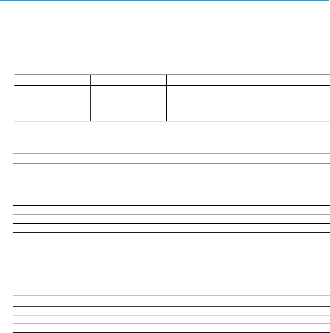
Chapter 16 Define a trend component
Publication 1756-RM014B-EN-P - November 2023 255
Refer to the L5K PEN structure.
PEN <pen_name> [(Description := "text", Pen_Attributes)];
END_PEN
Refer to the L5X and L5K pen elements and descriptions.
L5X Item
L5K Item
Description
N/A
pen_name
The name of the pen.
In L5X, use a Name attribute on the <Pen> element.
Description
Description
User information about the pen.
Refer to the pen attributes and descriptions.
Attribute
Description
Name L5X only. Specify the name of the pen.
In L5K, the name is an element of the statement.
Color Specify the color of the line in RGB format. Type the hex number for the color (16#0000_0000 –
16#00FF_FFFF).
Visible
Specify whether or not the line should be visible. Type TRUE or FALSE.
Width Specify the width of the line in pixels (1...10).
Type
Specify the line type. Type Analog, Digital, or Full-Width.
Style Specify the style of line.
Type: For:
0 …………….
1 … … … …
2 . . . . . . . . . . .
3 … . … . … . …
4 … .. … .. … ..
Marker Specify the line marker (0...83)
Min
Specify the minimum value for the pen. The minimum cannot be greater than or equal to the maximum.
Max Specify the maximum value for the pen. The maximum cannot be less than or equal to the minimum.
EngUnits Specify engineering units. For example, rpm, gallon, fps, and degrees.
Observe these guidelines when defining a trend:
• A trend can support as many as eight pen declarations.
• Export just the trend of a controller project by right-clicking the trend
in the Controller Organizer and choosing Export. This saves the trend
as a .L5X file (XML format) in the same format as described above for
the trend section in the complete project .L5K file.
• To import a trend .L5X file into a controller project, right-click Trends
in the Control Organizer and select Import.
L5K PEN structure
Pen elements
Pen attributes
Trend guidelines
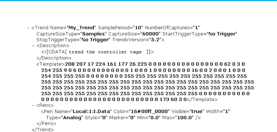
Chapter 16 Define a trend component
256 Publication 1756-RM014B-EN-P - November 2023
L5X Trend example
L5K TREND Example
TREND trend1 (SamplePeriod := 10,
NumberOfCaptures := 1,
CaptureSizeType := Samples,
CaptureSize := 60000,
StartTriggerType := No Trigger,
StopTriggerType := No Trigger,
TrendxVersion := 5.2)
Template :=
[208,207,17,224,161,177,26,225,0,0,0,0,0,0,0,0,0,0,0,0,
0,0,0,0,62,0,3,0,254,255,9,0,6,0,0,0,0,0,0,0,0,0,0,0,1,
0,0,0,1,0,0,0,0,0,0,0,0,16,0,0,2,0,0,0,1,0,0,0,254,255,
255,255,0,0,0,0,0,0,0,0,255,255,255,255,255,255,....
PEN Local:1:I.CHA_Status (Color := 16#00ff_0000,
Visible := 1,
Width := 1,
Type := Analog,
Style := 0,
Marker := 0,
Min := 0.0,
Max := 100.0)
END_PEN
PEN Local:1:I.CHB_Status (Color := 16#0000_ff00,
Visible := 1,
Width := 1,
Type := Analog,
Style := 0,
Marker := 0,
Min := 0.0,
Trend component examples

Chapter 16 Define a trend component
Publication 1756-RM014B-EN-P - November 2023 257
Max := 100.0)
END_PEN
END_TREND
Publication 1756-RM014B-EN-P - November 2023 259
Chapter 17
Define a watch list component
This chapter explains the overall structure of the watch list component.
The quick watch list component defines a collection of tags that you need to
monitor on the fly or for a period of time. A quick watch list is optional. You
can have multiple watch lists; each watch list can have multiple tags.
Refer to the L5X QuickWatchList structure.
<QuickWatchLists>
<QuickWatchList [QuickWatchListAttributes]>
<WatchTag [WatchTagAttributes] />>
</QuickWatchList>
</QuickWatchLists>
Refer to the L5K QUICK_WATCH structure.
QUICK_WATCH [(Quick_Watch_Attributes)]
WATCH_TAG [(Watch_Tag_Attributes)] ;
END_QUICK_WATCH
Refer to the L5X and L5K quick watch elements and descriptions.
L5X Item
L5K Item
Description
QuickWatchLists N/A The element that holds quick watch lists.
QuickWatchList
QUICK_WATCH
A quick watch list that holds watch tags.
WatchTag
WATCH_TAG
An individual watch tag within a watch list.
Refer to the quick watch list attribute and description.
Attribute Description
Name Specify the name of the quick watch list.
Watch list component
introduction
Quick watch list component
L5X QuickWatchList
structure
L5K QUICK_WATCH
structure
Quick Watch elements
Quick Watch List attributes
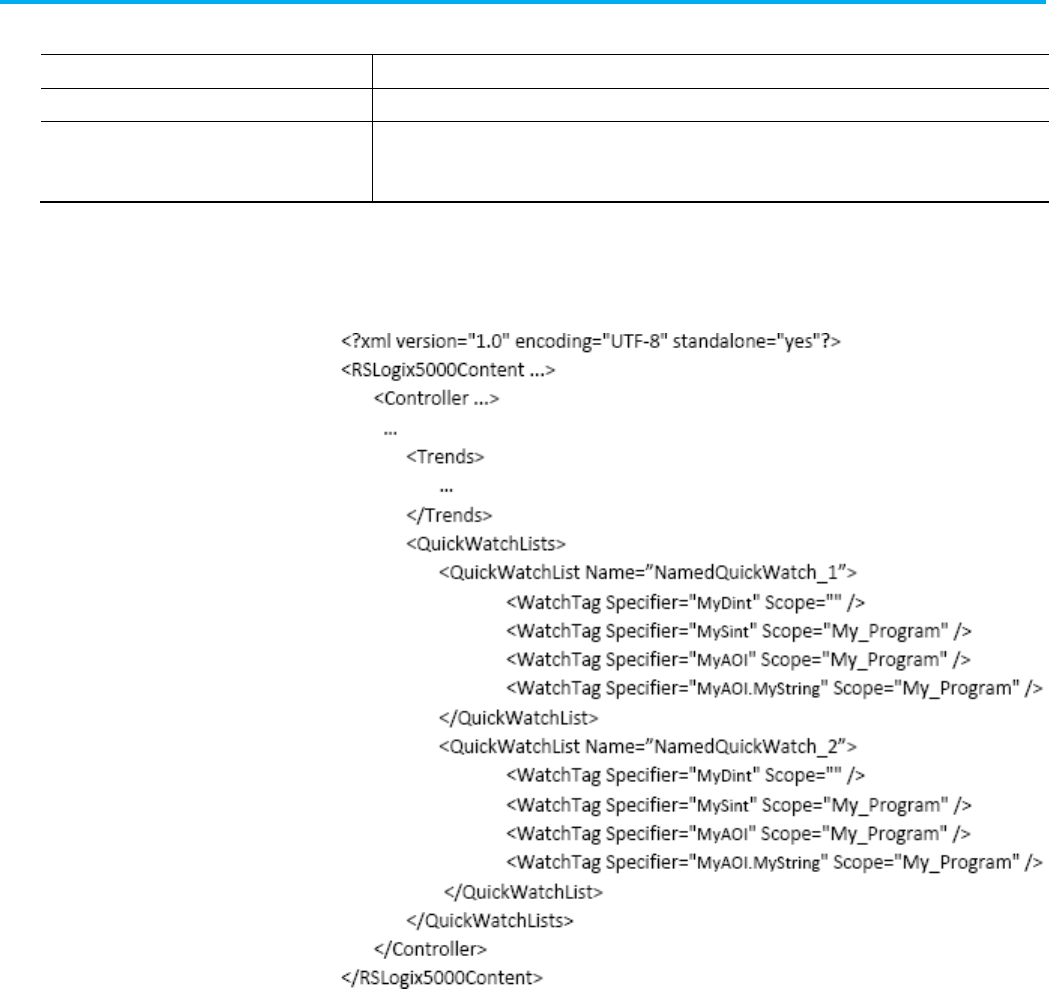
Chapter 17 Define a watch list component
260 Publication 1756-RM014B-EN-P - November 2023
Refer to the watch tag attributes and descriptions.
Attribute
Description
Specifier
Specify the tag or part of a tag to watch.
Scope Specify the name of program, equipment phase, or Add-On Instruction that contains the watch tag.
For L5X, the value is empty if the tag is controller scope.
For L5K, the attribute is omitted if the tag is controller scope.
L5X Quick watch lists example
L5K QUICK_WATCH example
QUICK_WATCH (Name := My_Quick_Watch_2)
WATCH_TAG (Specifier := MyDint);
WATCH_TAG (Specifier := MySint, Scope := My_Program);
WATCH_TAG (Specifier := MyAOI, Scope := My_Program);
WATCH_TAG (Specifier := MyAOI.MyString, Scope :=
MyProgram);
END_QUICK_WATCH
QUICK_WATCH (Name := My_Quick_Watch_1)
WATCH_TAG (Specifier := MyDint);
WATCH_TAG (Specifier := MySint, Scope := My_Program);
WATCH_TAG (Specifier := MyAOI, Scope := My_Program);
Watch tag attributes
Watch list component
examples

Chapter 17 Define a watch list component
Publication 1756-RM014B-EN-P - November 2023 261
WATCH_TAG (Specifier := MyAOI.MyString, Scope :=
MyProgram);
END_QUICK_WATCH

Publication 1756-RM014B-EN-P - November 2023 263
Chapter 18
Define controller configuration objects
This chapter explains how to enter project and configuration information in a
complete import/export file.
The config component defines controller objects.
Refer to the L5X config structure.
<CommPorts>
<SerialPort [SerialPort_Attributes]>
<ASCII [ASCII_Attributes]/>
<DF1 [DF1_Attributes]/>
</SerialPort>
</CommPorts>
<CST [CST_Attributes]/>
<WallClockTime [WallClockTime_Attributes]/>
Refer to L5K CONFIG structure.
CONFIG <object_name> [(Object_Attributes)]
END_CONFIG
Refer to the L5X and L5K object elements and descriptions.
L5X Item
L5K Item
Description
N/A
object_name
The name of the controller config object.
In L5X, each controller config object is specified with an element specific to that
object.
Controller objects are optional. There can be only one of each controller object
in an import/export file. Controller objects appear at the end of the
import/export file.
Controller configuration
objects introduction
Controller objects
L5X config structure
L5K CONFIG structure
Object elements
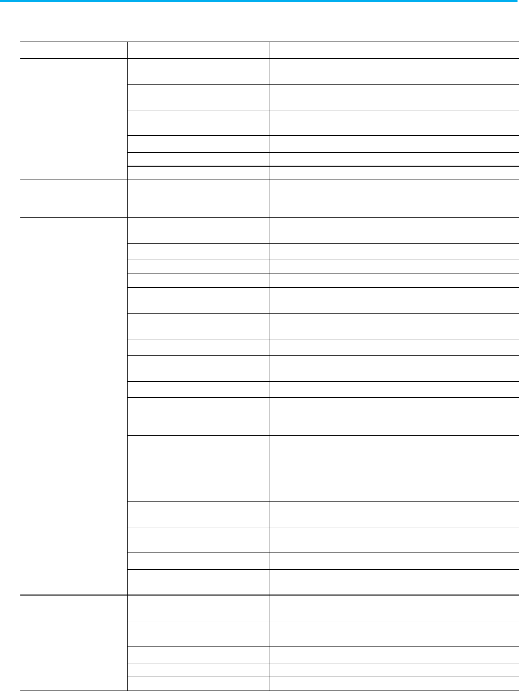
Chapter 18 Define controller configuration objects
264 Publication 1756-RM014B-EN-P - November 2023
The attributes depend on the type on the object. Some objects do not have any
attributes.
Object
Attribute
Description
ASCII XONXOFFEnable Specify whether to regulate the flow of incoming data. Type
0
to disable
XON/XOFF; type 1 to enable XON/XOFF.
DeleteMode
Specify the delete mode. Type 0 for Ignore; type 1 for CRT; or type 2 for Printer.
EchoMode Specify whether to echo data back to the device from which it was sent. Type
0
to
disable; type
1
to enable.
TerminationChars Specify the characters that designate the end of a line.
AppendChars Specify the characters to append to the end of a line.
BufferSize
Specify the maximum size of the data array (1...65535 bytes) to send and receive.
CST SystemTimeMasterIDn (L5K)
MasterID (L5X)
Specify whether the controller is the coordinated system time master. Type
16#0000
if the controller is not the CST master; type
16#0001
if the controller is
the CST master.
DF1 DuplicateDetection Specify whether to enable duplicate message detection, which ignores duplicate
messages. Type
0
to disable; type
1
to enable.
ErrorDetection
Specify the error detection method. Type BCC Error or CRC Error.
EnbeddedResponseEnable
Specify the response method. Type 0 to autodetect; type 1 to enable.
DF1Mode
Specify the DF1 mode. Type Pt to Pt, Master, or Slave.
ACKTimeout Specify the time to wait for an acknowledgment to a message transmission. Type
an increment of 20 ms (0...32767).
NAKReceiveLimit Specify the number of NAKS (0...127) the controller can receive in response to a
message before stopping transmission.
ENQTransmit Specify the number of inquiries (0...127) the controller sends after an ACK timeout.
TransmitRetries Specify the number of attempted retries (0...127) without getting an
acknowledgment before the message is deemed undeliverable.
StationAddress Specify the current station link address (0...254).
ReplyMessageWait Specify the time the master waits after receiving an acknowledgment to a
master-initiated message before polling the slave for a response. Type an
increment of 20 ms (0...65535).
PollingMode Specify the polling mode. Type one of these:
• 1 for Message Based (slave can initiate messages)
• 2 for Message Based (slave cannot initiate messages)
• 3 for Standard (multiple message transfer for node scan)
• 4 for Standard (single message transfer per node scan)
MasterMessageTransmit Specify when the master transmits. Type
0
to transmit between station polls; type
1 to transmit in poll sequence.
NormalPollNodeFile Specify the tag name of the structure that contains the normal poll node list, or
type <NA>. The tag must specify Class = Standard.
NormalPollGroupSize Specify the total number (0...255) of active stations polled from the poll list.
PriorityPollNodeFile Specify the tag name of the structure that contains the priority poll node list, or
type <NA>. The tag must specify Class = Standard.
DF1
ActiveStationFile Specify the tag name of the structure that contains the status (active or
non-active) of each node, or type <NA>. The tag must specify Class = Standard.
SlavePollTimeout Specify the amount of time the master waits for an acknowledgment to a
message sent to a slave. Type an increment of 20 ms (0...65535).
EOTSuppression Specify whether to enable EOT suppression. Type
0
to disable; type
1
to enable.
MaxStationAddress
Specify the maximum station address (0...31).
TokenHoldFactor
Specify the token hold factor (1...4).
Config attributes

Chapter 18 Define controller configuration objects
Publication 1756-RM014B-EN-P - November 2023 265
Object
Attribute
Description
EnableStoreFwd
For DF1 radio modem, specify whether to enable the store and forward feature.
Type
0
to disable; type
1
to enable.
StoreFwdFile
Specify the INT tag that holds the store and forward table.
SerialPort Channel (L5X only) Specify the serial port.
BaudRate Specify the communication rate for the serial port. Type
110, 300 600, 1200,
2400, 4800, 9600, 19200, or 38400.
Parity Specify the parity setting for the serial port. Parity provides additional
message-packet error detection. Type None Parity, Even Parity, or Odd Parity.
DataBits Specify the number of bits per message packet. Type
7 Data Bits
or
8 Data Bits
.
StopBits Specify the number of stop bits to the device with which the controller is
communicating. Type 1 Stop Bit or 2 Stop Bit.
ComDriverId Specify the type of serial driver. Type
DF1
.
PendingComDriverId
L5K only. Specify type of serial driver. Type DF1.
RTSOffDelay
Specify a time delay to make sure the modem successfully transmits the entire
message. Type an increment of 20 ms (0...32767). Normally leave at zero.
RTSSendDelay
Specify a time delay to let the modem prepare to transmit a message. Type an
increment of 20 ms (0...32767).
ControlLine Specify the mode in which the serial driver operates. Type
No Handshake
,
Full
Duplex
,
Half Duplex without Continuous Carrier
, or
Half Duplex with
Continuous Carrier.
PendingControlLine L5K only. Specify the mode in which the serial driver operates. Type
No
Handshake
,
Full Duplex
,
Half Duplex without Continuous Carrie
r, or
Half Duplex
with Continuous Carrier.
RemoteModeChangeFlag Specify whether there is a remote change. Type
0
or
1
.
PendingRemoteModeChangeFlag
L5K only. Specify whether there is a remote change. Type 0 or 1.
ModeChangeAttentionChar Specify the mode change attention character.
PendingModeChangeAttentionChar L5K only. Specify the mode change attention character.
SerialPort SystemModeCharacter Specify the system mode character.
PendingSystemModeCharacter L5K only. Specify the system mode character.
UserModeCharacter
Specify the user mode character.
PendingSystemModeCharacter
L5K only. Specify the user mode character.
Serial Port (cont)
DCDWaitDelay
For DF1 radio modem, specify the delay in seconds (0...255). Specify this value if
ControlLine is Half-Duplex and ContinuousCarrier is disabled.
WallClockTime LocalTimeAdjustment Specify any local time adjustment.
TimeZone
Specify the time zone.
Internet Protocol ConfigType Specify the IP configuration type.
Values include
Manual
,
BOOTP
,
or
DHCP
.
IPAddress Specify the IP Address.
SubnetMask
Specify the Subnet Mask.
Gateway
Specify the Gateway.
PrimaryDNS Specify the Primary DNS.
SecondaryDNS
Specify the Secondary DNS.
DomainName
Specify the Domain Name.
HostName
Specify the Host Name.
Ethernet Port Port This is the Ethernet Port number being configured. (L5X only)
PortEnabled Specifies if the port is Enabled or Disabled.
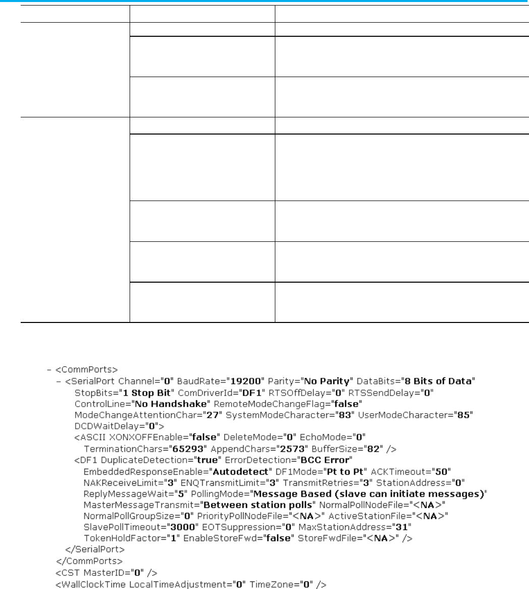
Chapter 18 Define controller configuration objects
266 Publication 1756-RM014B-EN-P - November 2023
Object
Attribute
Description
AutoNegotiateEnabled
Specifies if Auto Negotiate is Enabled or Disabled.
InterfaceSpeed Specifies the Interface Speed in Mbps.
Valid values are 10 or 100.
DuplexMode
Specifies the Duplex Mode.
Valid values are Half or Full.
Ethernet Network SupervisorModeEnabled Specify if the ring supervisor mode of the controller is Enabled.
SupervisorPrecedence Specifies the Supervisor Precedence.
A numerically higher value indicates higher precedence.
Values are in the range of 0...255.
BeaconInterval Specifies the Beacon Interval for the ring.
Values are in the range of 100...100000 usec.
BeaconTimeout Specifies the Beacon Timeout for the ring.
Values are in the range of 200...500000 usec.
VLANID Specifies the Ring Protocol VLAN ID of the ring.
Values are in the range of 0... 4094
L5X Config example
L5K CONFIG Examples
This example shows a DF1 controller object.
CONFIG DF1
DuplicateDetection := -1,
ErrorDetection := BCC Error,
EmbeddedResponseEnable := -1,
DF1Mode := Pt to Pt,
Controller objects examples

Chapter 18 Define controller configuration objects
Publication 1756-RM014B-EN-P - November 2023 267
ACKTimeout := 50,
NAKReceiveValue := 3,
DF1ENQs := 3,
DF1Retries := 3,
StationAddress := 0,
ReplyMessageWait := 50,
PollingMode := 0,
MasterMessageTransmit := 0,
NormalPollNodeFile := NA,
NormalPollGroupSize := 0,
PriorityPollNodeFile := NA,
ActiveStationFile := NA)
END_CONFIG
This example shows a SerialPort controller object.
CONFIG SerialPort
(BaudRate := 19200,
Parity := No Parity,
DataBits := 8 Bits of Data,
StopBits := 1 Stop Bit,
ComDriverId := DF1,
RTSOffDelay := 0,
RTSSendDelay := 0,
ControlLine := No Handshake,
RemoteModeChangeFlag := 0,
ModeChangeAttentionChar := 27,
SystemModeCharacter := 83,
UserModeCharacter := 85)
END_CONFIG

Publication 1756-RM014B-EN-P - November 2023 269
Chapter 19
Define custom properties
This chapter explains how to define custom properties in a controller project.
Custom properties can be used to store any additional information that
should persist with the project. This information is imported with the project,
downloaded to the controller, uploaded from the controller, and exported
with the project. Custom properties can be added to most XML elements in
the L5X format. For example, you can add it to the controller, data types,
data type members, modules, add-on instructions, tags, programs, routines,
rungs, sheets, various instructions, various collections, ST lines, trends, and
so on. However, you cannot add custom properties to custom properties.
Custom properties are compatible only with the L5X format.
Custom property data is well-formed XML limited to chunks of 65000 bytes.
To associate more thank 65K of data on a single parent object, break it into
multiple sections using the extension attribute. This optional attribute is a
free-form string, so you can organize custom properties information in any
way you need.
The following sections describe custom properties data.
Custom Properties should be the first child xml element under the parent
element.
<ParentXmlObject … >
<CustomProperties>
<Provider ID="YourCompanyName" Ext="Part 1" >
<YourData YourAttrib="Your Value" />
<YourOtherData Attrib2="2" >
<YourChildElement Attrib3="3" />
</YourOtherData>
</Provider>
<Provider ID="YourCompanyName" Ext="Part 2" >
<![CDATA[ Your custom property data
wrapped in CData ]]>
</Provider>
<Provider ID="ToolMakerX" >
<ToolMakerData >Custom property data
from a tool you are using</ToolMakerData>
</Provider>
Custom properties
introduction
Custom properties data
Custom properties
structure
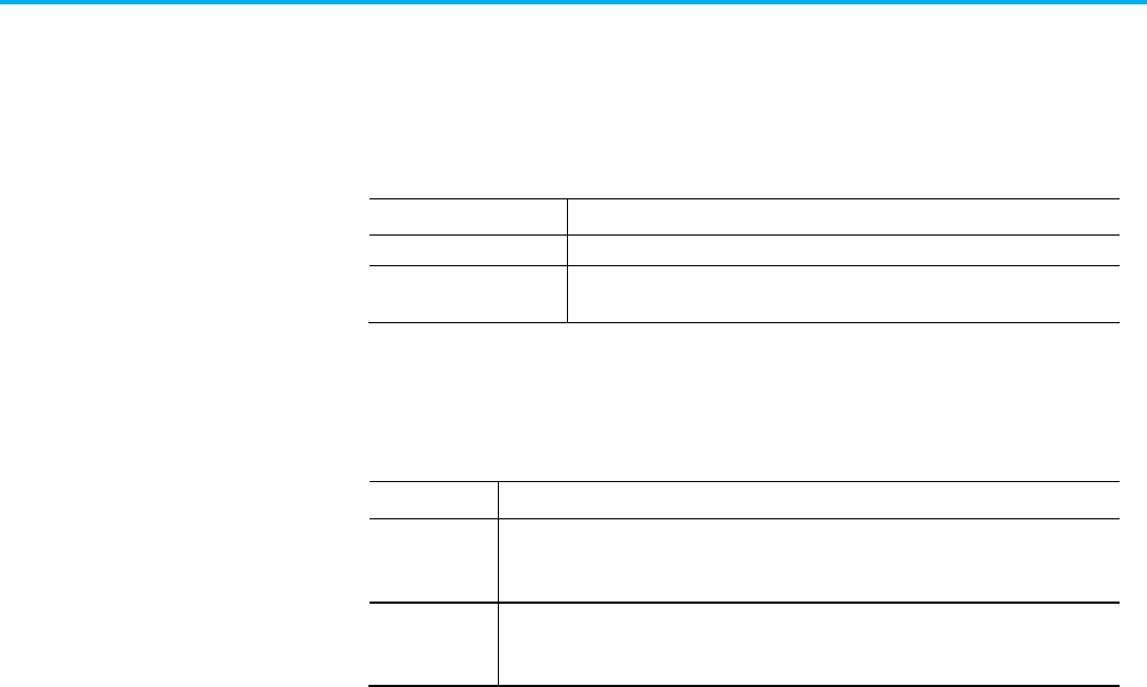
Chapter 19 Define custom properties
270 Publication 1756-RM014B-EN-P - November 2023
</CustomProperties>
… (the rest of the ParentObject’s child elements) …
</ParentXmlObject >
This table contains .L5X custom property elements and their descriptions.
L5X item
Description
CustomProperties
The collection of Provider elements.
Provider Unique element that wraps the user’s custom property XML. The XML between this
beginning and end element must be well-formed.
This table contains custom properties attributes and descriptions.
Attribute
Description
ID The provider attribute which identifies the owner of this custom property data. This is a
free-form string. It could identify your company, or it might come from a third party (OEM)
component or tool that you are using.
Ext (Optional) This extension attribute flags custom property data when you need to break it into
multiple Provider sections. This is a free-form string. An attribute with an empty string is
the same as not having the attribute.
This example demonstrates adding custom properties for a tag:
<Tag Name="MyTag" TagType="Base" DataType="DINT"
Radix="Decimal" Constant="false"
ExternalAccess="Read/Write">
<CustomProperties>
<Provider ID="CompanyX" >
<CompanXTextData > Your Xml data as a
Text Node </CompanXTextData>
</Provider>
</CustomProperties>
<Data Format="L5K">
<![CDATA[42]]>
</Data>
<Data Format="Decorated">
<DataValue DataType="DINT" Radix="Decimal"
Value="42"/>
</Data>
</Tag>
Custom properties
elements
Custom properties
attributes
Custom properties example

Publication 1756-RM014B-EN-P - November 2023 271
Chapter 20
Define Safety Signatures
This chapter explains how to define safety signatures in a controller project.
In Logix Designer versions 36 and later, the safety signature is a hierarchy of
multiple safety signature elements. For example, the safety task, programs,
and routines are examples of safety signature elements. Use imitated safety
element signatures during impact analysis to help identify the individual
changes within a controller project. It might reduce your certification effort if
your validation plan does not require re-validation of unchanged elements. To
view all safety signature elements for a project, run the Safety Signature
report in the Logix Designer application.
These attributes describe signatures in exports and imports:
• Overall signature. Appears in exports as the SafetySignature attribute
where the signature and the time stamp are concatenated. Appears
under the SafetyInfo node for L5X and under the CONTROLLER
element for L5K.
• Root signature. The root signature is the same as the overall signature
except that:
• It is exported even if is stale.
• It can also be imported.
• It is exported with a time stamp that represents the time when the
signature value was generated. If the signature is regenerated
(deleted, then generated again) and the same signature value is
received, then the original time stamp is used.
These examples show the overall signature and root signature attributes:
L5X:
<Controller>
<SafetyInfo SafetySignature="B3CC8FA3 - 65D512A2 -
25A1A8A7 - A4B46668 - 6F7F560A - 721374FD - B2ED3906 -
36CBACCC, 02/23/2023, 02:41:57.402 PM">
<RootSignature Signature="B3CC8FA3 - 65D512A2 -
25A1A8A7 - A4B46668 - 6F7F560A - 721374FD - B2ED3906 -
36CBACCC"
Timestamp="02/09/2023,
01:45:38.445 PM" />
</SafetyInfo>
</Controller>
Safety Signatures
introduction

Chapter 20 Define Safety Signatures
272 Publication 1756-RM014B-EN-P - November 2023
L5K:
CONTROLLER safety_v36 (SafetySignature := "B3CC8FA3 -
65D512A2 - 25A1A8A7 - A4B46668 - 6F7F560A - 721374FD -
B2ED3906 - 36CBACCC, 02/23/2023, 02:41:57.402 PM",
SafetyRootSignature := "B3CC8FA3
- 65D512A2 - 25A1A8A7 - A4B46668 - 6F7F560A - 721374FD -
B2ED3906 - 36CBACCC",
SafetyRootSignatureTimestamp :=
"02/09/2023, 01:45:38.445 PM")
END_CONTROLLER
These examples show safety signature attributes in L5X and L5K code.
Safety Application rollup, controller attribute signature, and safety
tag map signature
L5X:
<Controller>
<SafetyInfo>
<SafetyTagMap> ctrlTagStandard=ctrlTagSafety,
ctrlTagStandard2=ctrlTagSafety2</SafetyTagMap>
<SafetyTagMapSignature Signature="F5AFC204 -
9393CBA7 - 0CC9E546 - 31B67107 - 1EE4D63C - 63C58FAA -
6717B619 - 686CC114"
Timestamp="02/09/2023,
01:45:38.445 PM" />
<ControllerAttributesSignature
Signature="F5AFC204 - 9393CBA7 - 0CC9E546 - 31B67107 -
1EE4D63C - 63C58FAA - 6717B619 - 686CC114"
Timestamp="02/09/2023, 01:45:38.445 PM" />
<ApplicationRollupSignature Signature="F5AFC204
- 9393CBA7 - 0CC9E546 - 31B67107 - 1EE4D63C - 63C58FAA -
6717B619 - 686CC114"
Timestamp="02/09/2023, 01:45:38.445 PM" />
</SafetyInfo>
</Controller>
L5K:
CONTROLLER safety_v36 (SafetyTagMap := "
ctrlTagStandard=ctrlTagSafety,
ctrlTagStandard2=ctrlTagSafety2",
SafetyTagMapSignature :=
"F5AFC204 - 9393CBA7 - 0CC9E546 - 31B67107 - 1EE4D63C -
63C58FAA - 6717B619 - 686CC114",
Safety Signature examples

Chapter 20 Define Safety Signatures
Publication 1756-RM014B-EN-P - November 2023 273
SafetyTagMapSignatureTimestamp
:= "02/09/2023, 01:45:38.445 PM",
ControllerAttributesSignature :=
"F5AFC204 - 9393CBA7 - 0CC9E546 - 31B67107 - 1EE4D63C -
63C58FAA - 6717B619 - 686CC114",
ControllerAttributesSignatureTimestamp := "02/09/2023,
01:45:38.445 PM",
ApplicationRollupSignature :=
"F5AFC204 - 9393CBA7 - 0CC9E546 - 31B67107 - 1EE4D63C -
63C58FAA - 6717B619 - 686CC114",
ApplicationRollupSignatureTimestamp := "02/09/2023,
01:45:38.445 PM")
END_CONTROLLER
Controller aggregated safety tags signature
L5X:
<Controller>
<Tags SafetySignature="F5AFC204 - 9393CBA7 - 0CC9E546
- 31B67107 - 1EE4D63C - 63C58FAA - 6717B619 - 686CC114"
SafetySignatureTimestamp="02/09/2023,
01:45:38.445 PM">
</Tags>
</Controller>
L5K:
CONTROLLER safety_v36 (TagsRollupSignature := "F5AFC204 -
9393CBA7 - 0CC9E546 - 31B67107 - 1EE4D63C - 63C58FAA -
6717B619 - 686CC114",
TagsRollupSignatureTimestamp :=
"02/09/2023, 01:45:38.445 PM")
END_CONTROLLER
Signatures for safety tasks, programs, aggregated tags and
parameters, and routines
L5X:
<Controller>
<Programs>
<Program Class="Safety"

Chapter 20 Define Safety Signatures
274 Publication 1756-RM014B-EN-P - November 2023
SafetySignature="F5AFC204 - 9393CBA7 -
0CC9E546 - 31B67107 - 1EE4D63C - 63C58FAA - 6717B619 -
686CC114"
SafetySignatureTimestamp="02/09/2023,
01:45:38.445 PM">
<Tags SafetySignature="F5AFC204 - 9393CBA7 -
0CC9E546 - 31B67107 - 1EE4D63C - 63C58FAA - 6717B619 -
686CC114"
SafetySignatureTimestamp="02/09/2023,
01:45:38.445 PM">
</Tags>
<Routines>
<Routine SafetySignature="F5AFC204 -
9393CBA7 - 0CC9E546 - 31B67107 - 1EE4D63C - 63C58FAA -
6717B619 - 686CC114"
SafetySignatureTimestamp="02/09/2023, 01:45:38.445 PM"
/>
</Routines>
</Program>
</Programs>
<Tasks>
<Task Class="Safety"
SafetySignature="F5AFC204 - 9393CBA7 -
0CC9E546 - 31B67107 - 1EE4D63C - 63C58FAA - 6717B619 -
686CC114"
SafetySignatureTimestamp="02/09/2023,
01:45:38.445 PM">
</Task>
</Tasks>
</Controller>
L5K:
PROGRAM SafetyProgram (Class := Safety,
ProgramSignature := "F5AFC204
- 9393CBA7 - 0CC9E546 - 31B67107 - 1EE4D63C - 63C58FAA -
6717B619 - 686CC114",
ProgramSignatureTimestamp :=
"02/09/2023, 01:45:38.445 PM",
TagsSignature := "F5AFC204 -
9393CBA7 - 0CC9E546 - 31B67107 - 1EE4D63C - 63C58FAA -
6717B619 - 686CC114",
TagsSignatureTimestamp :=
"02/09/2023, 01:45:38.445 PM")
TAG
localTagSafety : DINT (RADIX := Decimal) := 0;
END_TAG

Chapter 20 Define Safety Signatures
Publication 1756-RM014B-EN-P - November 2023 275
ROUTINE MainRoutine (RoutineSignature :=
"F5AFC204 - 9393CBA7 - 0CC9E546 - 31B67107 - 1EE4D63C -
63C58FAA - 6717B619 - 686CC114",
RoutineSignatureTimestamp
:= "02/09/2023, 01:45:38.445 PM")
END_ROUTINE
CHILD_PROGRAMS
END_CHILD_PROGRAMS
END_PROGRAM
TASK SafetyTask (Class := Safety,
TaskSignature := "F5AFC204 -
9393CBA7 - 0CC9E546 - 31B67107 - 1EE4D63C - 63C58FAA -
6717B619 - 686CC114",
TaskSignatureTimestamp :=
"02/09/2023, 01:45:38.445 PM")
END_TASK
Signatures for safety Add on Instructions (normal and encoded),
aggregated tags and parameters, and routines
L5X:
<Controller>
<AddOnInstructionDefinitions
SafetySignature="F5AFC204 - 9393CBA7 - 0CC9E546 - 31B67107
- 1EE4D63C - 63C58FAA - 6717B619 - 686CC114"
SafetySignatureTimestamp="02/09/2023, 01:45:38.445 PM">
<AddOnInstructionDefinition Class="Safety"
SafetySignature="F5AFC204 - 9393CBA7 - 0CC9E546 - 31B67107
- 1EE4D63C - 63C58FAA - 6717B619 - 686CC114"
SafetySignatureTimestamp="02/09/2023, 01:45:38.445 PM">
<ParametersAndLocalTagsRollupSignature
Signature="F5AFC204 - 9393CBA7 - 0CC9E546 - 31B67107 -
1EE4D63C - 63C58FAA - 6717B619 - 686CC114"
Timestamp="02/09/2023, 01:45:38.445 PM" />
<Parameters>
</Parameters>
<LocalTags>
</LocalTags>
<Routines>

Chapter 20 Define Safety Signatures
276 Publication 1756-RM014B-EN-P - November 2023
<Routine SafetySignature="F5AFC204 -
9393CBA7 - 0CC9E546 - 31B67107 - 1EE4D63C - 63C58FAA -
6717B619 - 686CC114"
SafetySignatureTimestamp="02/09/2023, 01:45:38.445 PM">
</Routine>
</Routines>
</AddOnInstructionDefinition>
<EncodedData Class="Safety"
SafetySignature="F5AFC204 -
9393CBA7 - 0CC9E546 - 31B67107 - 1EE4D63C - 63C58FAA -
6717B619 - 686CC114"
SafetySignatureTimestamp="02/09/2023, 01:45:38.445 PM">
<Parameters>
</Parameters>
ENCODED_DATA_HERE
</EncodedData>
</AddOnInstructionDefinitions>
</Controller>
L5K:
CONTROLLER safety_v36 (AoisRollupSignature := "F5AFC204 -
9393CBA7 - 0CC9E546 - 31B67107 - 1EE4D63C - 63C58FAA -
6717B619 - 686CC114",
AoisRollupSignatureTimestamp :=
"02/09/2023, 01:45:38.445 PM")
ADD_ON_INSTRUCTION_DEFINITION SafetyAOI (Class :=
Safety,
AoiSignature := "F5AFC204 - 9393CBA7 - 0CC9E546 - 31B67107
- 1EE4D63C - 63C58FAA - 6717B619 - 686CC114",
AoiSignatureTimestamp := "02/09/2023, 01:45:38.445 PM",
AoiParametersAndLocalTagsRollupSignature := "F5AFC204 -
9393CBA7 - 0CC9E546 - 31B67107 - 1EE4D63C - 63C58FAA -
6717B619 - 686CC114",
AoiParametersAndLocalTagsRollupSignatureTimestamp :=
"02/09/2023, 01:45:38.445 PM")
PARAMETERS
EnableIn : BOOL (Description := "Enable Input
- System Defined Parameter",
Usage := Input,
RADIX := Decimal,
Required := No,

Chapter 20 Define Safety Signatures
Publication 1756-RM014B-EN-P - November 2023 277
Visible := No,
ExternalAccess := Read
Only);
END_PARAMETERS
LOCAL_TAGS
OloSafety : DINT (RADIX := Decimal,
ExternalAccess := None,
DefaultData := 0);
END_LOCAL_TAGS
ROUTINE Logic (RoutineSignature := "F5AFC204 -
9393CBA7 - 0CC9E546 - 31B67107 - 1EE4D63C - 63C58FAA -
6717B619 - 686CC114",
RoutineSignatureTimestamp :=
"02/09/2023, 01:45:38.445 PM")
N: XIC(ParamForAOI)OTL(ParamForAOI);
N: XIC(LocalTagAOI)OTU(LocalTagAOI);
END_ROUTINE
END_ADD_ON_INSTRUCTION_DEFINITION
ENCODED_DATA (EncodedType :=
ADD_ON_INSTRUCTION_DEFINITION,
Name := "EncodedSafetyAOI",
Class := Safety,
AoiSignature := "F5AFC204 - 9393CBA7 -
0CC9E546 - 31B67107 - 1EE4D63C - 63C58FAA - 6717B619 -
686CC114",
AoiSignatureTimestamp := "02/09/2023,
01:45:38.445 PM")
PARAMETERS
EnableIn : BOOL (Description := "Enable Input
- System Defined Parameter",
Usage := Input,
RADIX := Decimal,
Required := No,
Visible := No,
ExternalAccess := Read
Only);
END_PARAMETERS
ENCODED_DATA_HERE
END_ENCODED_DATA
END_CONTROLLER

Chapter 20 Define Safety Signatures
278 Publication 1756-RM014B-EN-P - November 2023
Signatures for aggregated safety modules, aggregated safety
module connections, and safety connections
L5X:
<Controller>
<Modules SafetySignature="F5AFC204 - 9393CBA7 -
0CC9E546 - 31B67107 - 1EE4D63C - 63C58FAA - 6717B619 -
686CC114"
SafetySignatureTimestamp="02/09/2023,
01:45:38.445 PM">
<Module SafetySignature="F5AFC204 - 9393CBA7 -
0CC9E546 - 31B67107 - 1EE4D63C - 63C58FAA - 6717B619 -
686CC114"
SafetySignatureTimestamp="02/09/2023,
01:45:38.445 PM">
<Communications>
<Connections SafetySignature="F5AFC204 -
9393CBA7 - 0CC9E546 - 31B67107 - 1EE4D63C - 63C58FAA -
6717B619 - 686CC114"
SafetySignatureTimestamp="02/09/2023, 01:45:38.445 PM">
<Connection
SafetySignature="F5AFC204 - 9393CBA7 - 0CC9E546 - 31B67107
- 1EE4D63C - 63C58FAA - 6717B619 - 686CC114"
SafetySignatureTimestamp="02/09/2023, 01:45:38.445 PM">
</Connection>
</Connections>
</Communications>
</Module>
</Modules>
</Controller>
L5K:
CONTROLLER safety_v36 (ModulesRollupSignature :=
"F5AFC204 - 9393CBA7 - 0CC9E546 - 31B67107 - 1EE4D63C -
63C58FAA - 6717B619 - 686CC114",
ModulesRollupSignatureTimestamp
:= "02/09/2023, 01:45:38.445 PM")
MODULE safetyIO (ModuleSignature := "F5AFC204 -
9393CBA7 - 0CC9E546 - 31B67107 - 1EE4D63C - 63C58FAA -
6717B619 - 686CC114",
ModuleSignatureTimestamp :=
"02/09/2023, 01:45:38.445 PM"
ConnectionsRollupSignature :=
"F5AFC204 - 9393CBA7 - 0CC9E546 - 31B67107 - 1EE4D63C -
63C58FAA - 6717B619 - 686CC114",

Chapter 20 Define Safety Signatures
Publication 1756-RM014B-EN-P - November 2023 279
ConnectionsRollupSignatureTimestamp := "02/09/2023,
01:45:38.445 PM")
CONNECTION SafetyInput (ConnectionSignature
:= "F5AFC204 - 9393CBA7 - 0CC9E546 - 31B67107 - 1EE4D63C
- 63C58FAA - 6717B619 - 686CC114",
ConnectionSignatureTimestamp := "02/09/2023,
01:45:38.445 PM")
END_CONNECTION
END_MODULE
END_CONTROLLER
Imported signatures are protected with a hash-based message authentication
code (HMAC) that authenticates the origin of the signature. You can import
only signatures that are generated by a controller and exported with an
authentication code. The Logix Designer application verifies authentication
codes after every type of import: full import, partial import, or paste.
If you make changes to exported L5X or L5K files, be careful not to change the
order of imports, which must match the export order. Any changes in the
import order will change the HMAC. Authentication failure appears in the
error pane in the Logix Designer application, and no signatures are imported.
Tip: The authentication codes are different for L5X and L5K files even when they are exported from
the same project.
Any of these changes in an L5X or L5K file can cause validation to fail and
prevent import of signatures:
• Changing the order of modules.
• Adding or re moving signed components.
• Modifying a signature or its timestamp.
Changing white space in a signature or a time stamp does not affect the
HMAC.
Signature authentication code contains HMAC code as well as the
configuration used to calculate the HMAC code. The configuration code
appears in the first two characters of authentication code, followed by 64
characters of HMAC code. The total authentication code is a 66-character
string that represents a 33-byte number in hexadecimal format. Signature
authentication code resembles other properties where HMAC is used.
In L5X files the authentication code is the last object in the Controller object in
the PropertyTable. In L5K files, the authentication code appears after all
CONTROLLER collections but before the CONFIG section.
L5X example:
Signature protection and
authentication
Authentication code
examples

Chapter 20 Define Safety Signatures
280 Publication 1756-RM014B-EN-P - November 2023
<RSLogix5000Content (...)>
<Controller (...)/>
(...)
<SafetySignaturesHmac
Value="040123456789ABCDEF0123456789ABCDEF0123456789ABCD
EF0123456789ABCDEF"/>
</Controller>
</RSLogix5000Content>
L5K example:
CONTROLLER XmlTest (...)
(...)
PROGRAM SafetyProgram(...) END_PROGRAM
TASK SafetyTask (...) END_TASK
AUTHENTICATION_CODE SafetySignaturesHmac(Value :=
"040123456789ABCDEF0123456789ABCDEF0123456789ABCDEF0123
456789ABCDEF") END_AUTHENTICATION_CODE
CONFIG CST(...) END_CONFIG
CONFIG WallClockTime(...) END_CONFIG
(Other CONFIGs...)
END_CONTROLLER
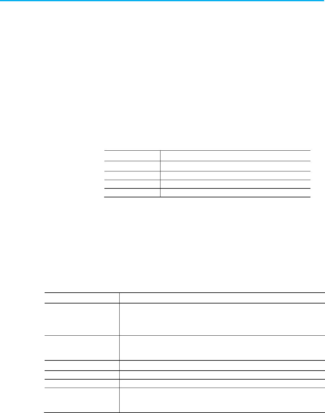
Publication 1756-RM014B-EN-P - November 2023 281
Chapter 21
Structure Tags and Comments in an
Import/Export File
This chapter explains how to structure the import/export file by using
commas (in a CSV text file) or tabs (in a TXT Unicode text file) to separate
values in the file.
The structured import/export file contains these components for comments
and other information.
Item
Identifies
Remark Comment within the file.
TAG
Tag.
RCOMMENT Rung comment.
TEXTBOX Text box comment.
Enter comments to document import files. The import process ignores these
comments. Place comments anywhere in an import/export file, except in
names and descriptions. Enter comments by starting the line (record) with
REMARK and a comma.
Each tag record defines a tag within a controller project. A tag record includes
this information.
Item
Identifies
Type The type of tag.
TAG tag
ALIAS alias tag
COMMENT tag operand component
Scope The part of the project that owns the tag.
• If no scope is specified, the scope is controller.
•
If a scope is specified, it identifies the program or equipment phase.
Name Name of the tag
Description
Description of the tag (optional)
Datatype
Datatype of the tag - use any valid datatype name
Specifier Optional
• An alias, specifies base tag.
• A tag comment, specifies the tag name and member or bit.
Structure tags and
comments introduction
Place information in a .CSV
or .TXT file
L5K Internal file comments
Specify a tag record
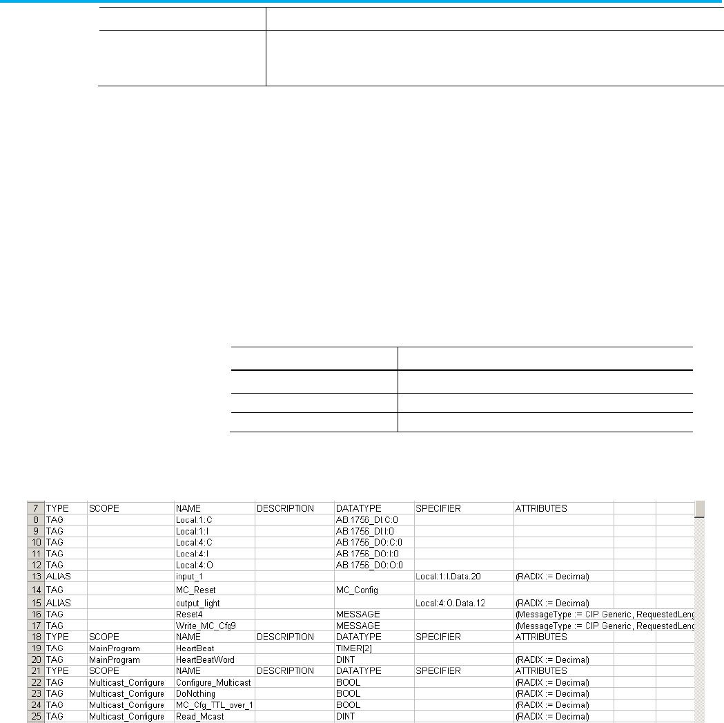
Chapter 21 Structure Tags and Comments in an Import/Export File
282 Publication 1756-RM014B-EN-P - November 2023
Item
Identifies
Attributes
The attributes of the tag, as exported in the L5K format.
Define how the tag can be used and how it appears.
Attributes do not include tag values.
Each TAG record defines a tag within a controller project.
TAG Structure with Commas
TAG,"Scope","Name","Description","Datatype","Specifie
r","Attributes"
TAG Structure with Tabs
TAG,"Scope" "Name" "Description" "Datatype"
"Specifier" "Attributes"
Specify tag dimensions on the Datatype.
To specify:
Type:
1 dimension [a]
2 dimensions
[a,b]
3 dimensions
[a,b,c]
This example shows TAG records in a CSV format.
Each ALIAS record defines an alias within a controller project.
ALIAS Structure with Commas
ALIAS,"Scope","Name","Description","Datatype","Specif
ier","Attributes"
ALIAS Structure with Tabs
ALIAS "Scope" "Name" "Description" "Datatype"
"Specifier" "Attributes"
This example shows ALIAS records in a CSV format.
TAG type record
ALIAS type record
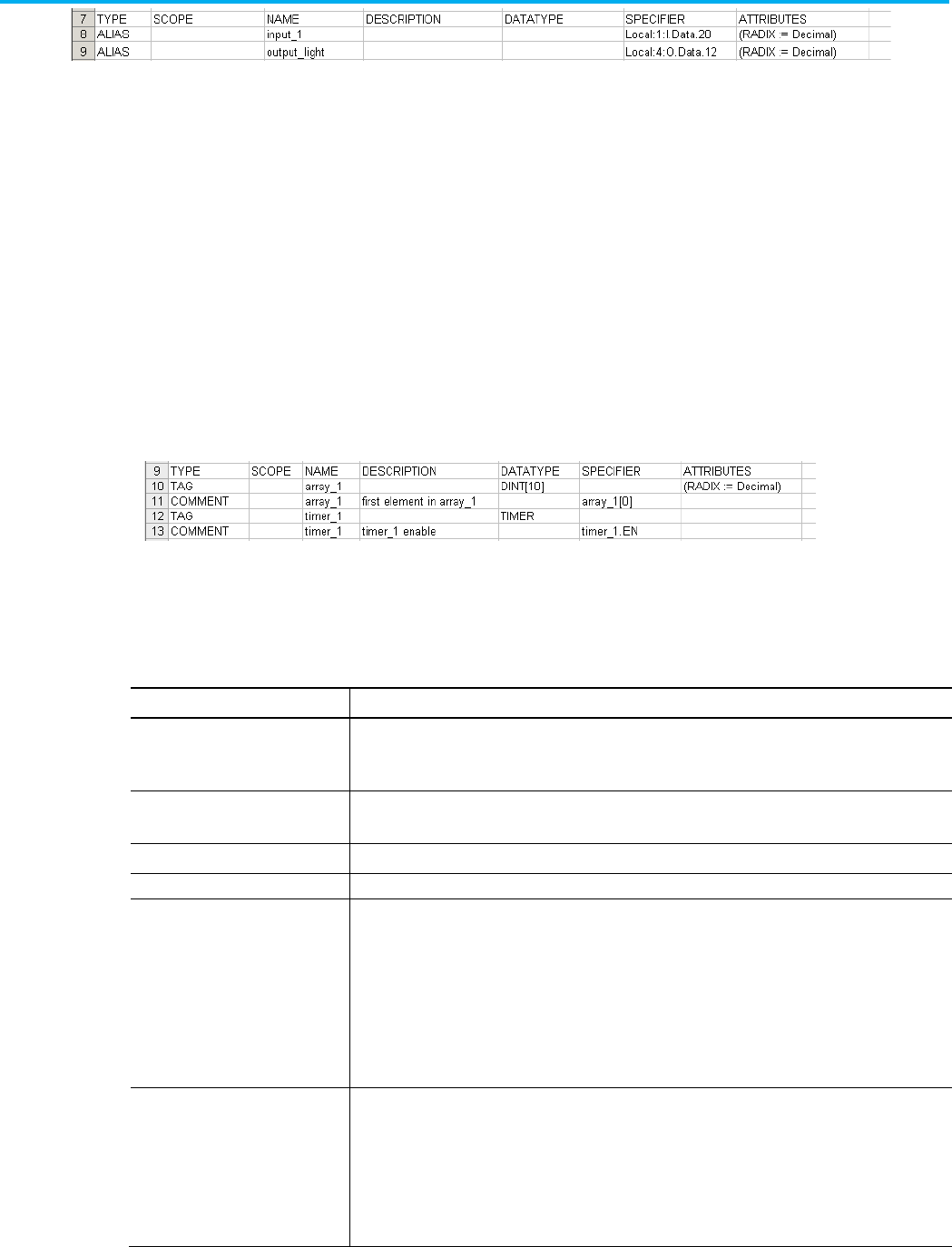
Chapter 21 Structure Tags and Comments in an Import/Export File
Publication 1756-RM014B-EN-P - November 2023 283
Each COMMENT record defines a comment about a component of a tag, such
as a bit member, structure member, or an array element.
COMMENT Structure with Commas
COMMENT,"Scope","Name","Description","Datatype","Spec
ifier","Attributes"
COMMENT Structure with Tabs
COMMENT "Scope" "Name" "Description","Datatype"
"Specifier" "Attributes"
This example shows COMMENT records in a CSV format.
Each comment record defines a rung comment or text box in the controller
project. This is different than the comment type that defines a comment
about a tag component. A comment record includes this information.
Item
Identifies
Type The type of comment.
RCOMMENT ladder rung comment
TEXTBOX function block or sequential function chart comment
Scope The part of the project that owns the comment.
A program or equipment phase must be specified.
Routine Name of the routine.
Comment
Text of the comment.
Owning Element For RCOMMENT entries, neutral text for the last instruction on the rung that owns the comment.
If there is no element on the rung, the Owning Element is a semi-colon (;).
By default, the Owning Element is used to match the comment to a rung on import.
For a TEXTBOX entry of an attached text box, neutral text identifies the element attached to the the text box.
The Owning Element contains the backing tag name and the full specifier of the element, including the
absolute location of the element.
Owning Element.
For a TEXTBOX entry of a free-floating text box, this entry is blank.
Location
For RCOMMENT entries, the rung number of comment. The rung number in the Location column is used to
match the comment to a rung if the Owning Element is blank for that comment or if you override the import
default by selecting Match all RLL rung comments by rung number only.
For TEXTBOX entries, the absolute location of free-floating text boxes or the relative location from the
owning element of attached text boxes. For absolute locations, the location contains both the sheet number
and the X and Y coordinates of the text box. For relative locations, the location contains only the X and Y
coordinates.
COMMENT type record
Specify a comment record
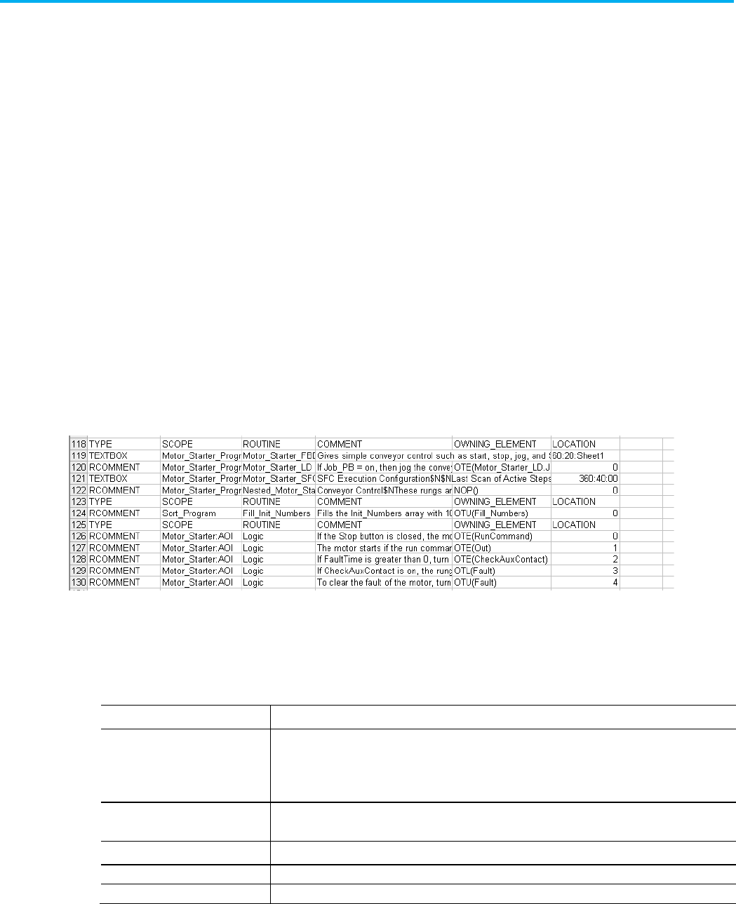
Chapter 21 Structure Tags and Comments in an Import/Export File
284 Publication 1756-RM014B-EN-P - November 2023
An RCOMMENT record follows this format.
RCOMMENT Structure with Commas
RCOMMENT,"Scope","Routine","Comment","Owning
Element","Location"
RCOMMENT Structure with Tabs
RCOMMENT "Scope" "Routine" "Comment"
"Owning Element" "Location"
A TESTBOX record follows this format.
TEXTBOX Structure with Commas
TEXBOX,"Scope","Routine","Comment","Owning
Element","Location"
TEXTBOX Structure with Tabs
TEXTBOX "Scope" "Routine" "Comment"
"Owning Element" "Location"
This example shows comment records in a CSV format.
An alarm tag can have several alarm message strings for different alarm
conditions in different languages. An alarm message record includes this
information.
Item
Identifies
Type The alarm message and its associated language as: ALMMSG:
language
Languages:
EN-US
(United States English),
DE
(Germany German),
ES
(Spain Spanish),
FR
(France French),
IT
(Italian),
PT
(Brazil Portuguese),
JA
(Japanese),
KO
(Korean),
ZH
(Chinese)
Scope The part of the project that owns the comment.
A program or equipment phase must be specified.
Name Name of the associated alarm tag.
Description
Text of the alarm message.
Datatype
The type of alarm. Specify ALARM_DIGITAL or ALARM_ANALOG.
Specify an alarm message
record
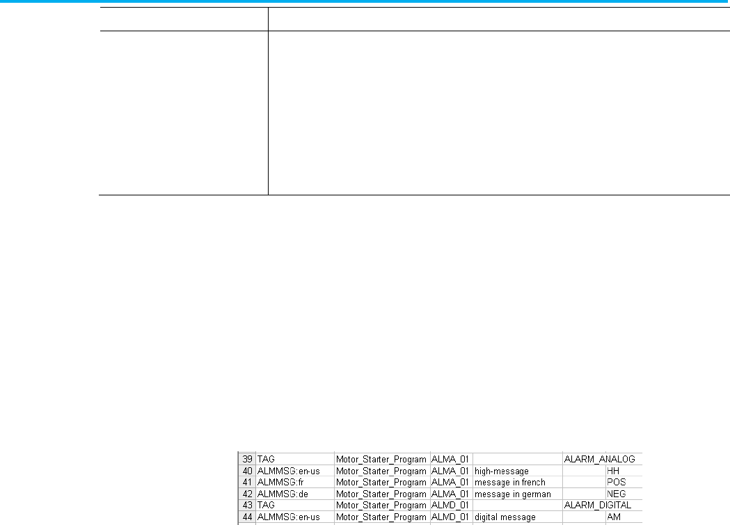
Chapter 21 Structure Tags and Comments in an Import/Export File
Publication 1756-RM014B-EN-P - November 2023 285
Item
Identifies
Specifier
Specify the type of alarm.
Specify: For:
AM Digital alarm
HH High-high analog alarm
H High analog alarm
L Low analog alarm
LL Low-low analog alarm
POS Rate-of-change positive analog alarm
NEG Rate-of change negative analog alarm
An ALMMSG record follows this format.
ALMMSG Structure with Commas
ALMMS:language,"Scope","Name","Description","Datatyp
e","Specifier"
ALMMSG Structure with Tabs
ALMMSG:language "Scope" "Name"
"Description" "Datatype" "Specifier"
This example shows alarm message records in a CSV format.
Example .CSV file
These examples use this ladder file.
Specify a tag record
examples
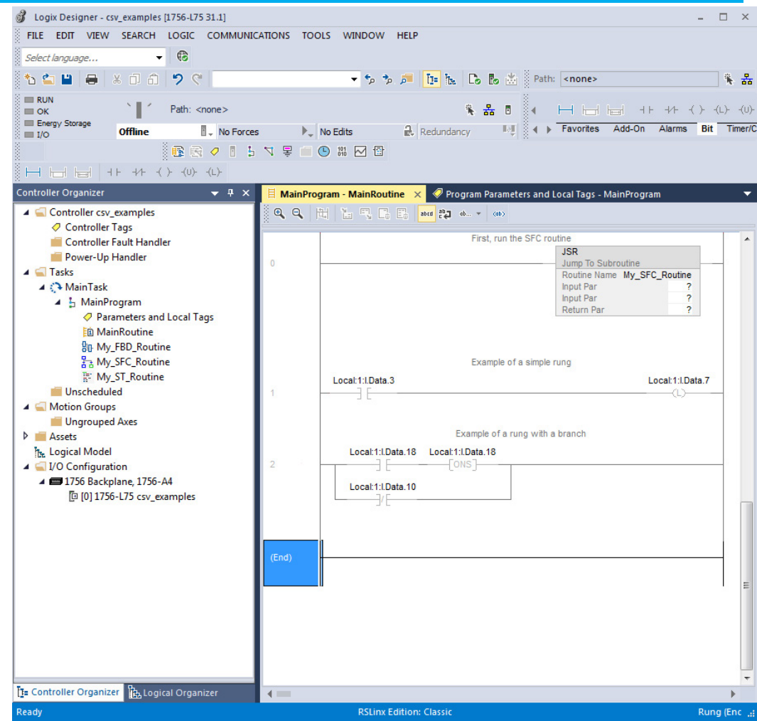
Chapter 21 Structure Tags and Comments in an Import/Export File
286 Publication 1756-RM014B-EN-P - November 2023
Export all tags and comments
An export of all tags and comments results in this .CSV file.
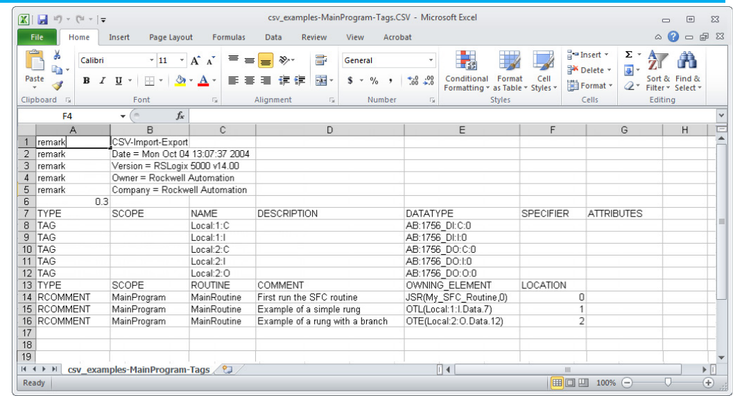
Chapter 21 Structure Tags and Comments in an Import/Export File
Publication 1756-RM014B-EN-P - November 2023 287
Example .TXT file
These examples use the Motor_Starter_Program program file and exports the
program parameters and local tags.
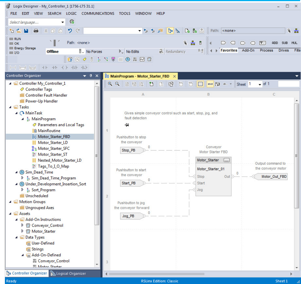
Chapter 21 Structure Tags and Comments in an Import/Export File
288 Publication 1756-RM014B-EN-P - November 2023
Export program tags and comments
An export of the Motor_Starter_Prorgam program tags and comments results
in this .TXT file.
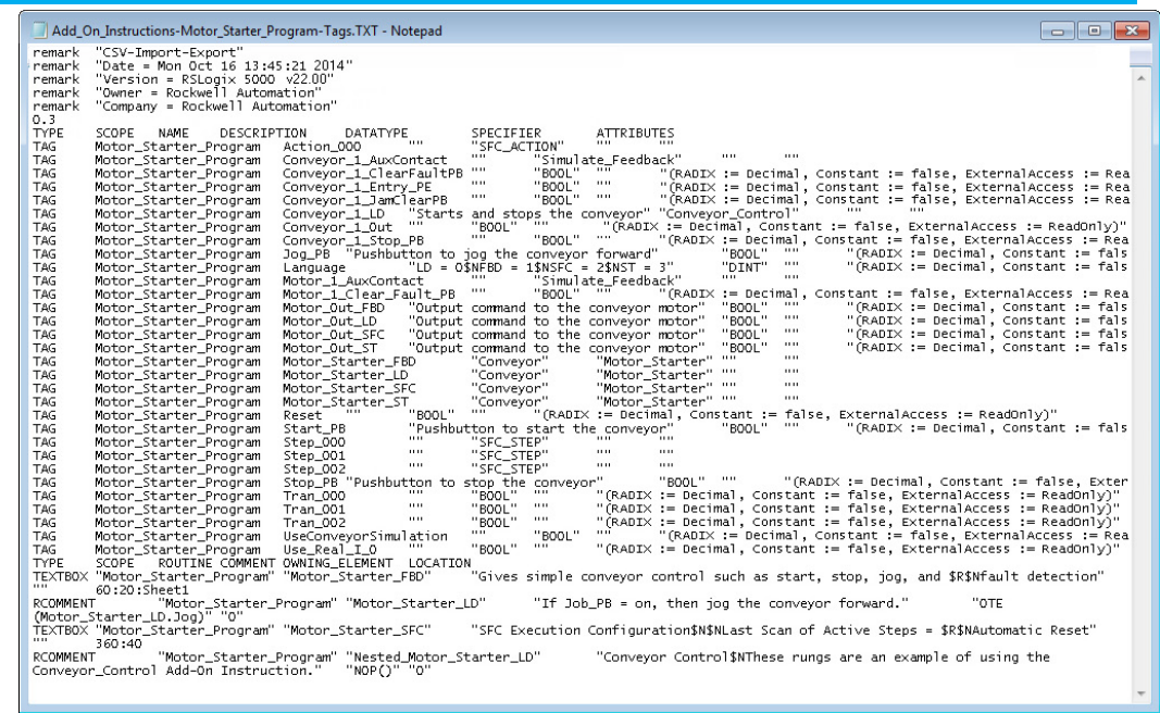
Chapter 21 Structure Tags and Comments in an Import/Export File
Publication 1756-RM014B-EN-P - November 2023 289
Publication 1756-RM014B-EN-P - November 2023 291
Appendix A
Considerations for using Microsoft Excel to edit
a .CSV file
This appendix describes how using Windows or Excel to edit a .CSV file can
affect the file.
IMPORTANT
To edit the .CSV file, it is recommended that you use a database program tool, such as
Access®, or a raw text editor. Many other desktop tools, such as Windows or Excel,
might change the structure of the .CSV file and cause an import of the file to fail.
To use Microsoft Excel to edit your .CSV tag file:
• Use single quotes instead of double quotes within descriptions
and comments.
• Do not create descriptions or comments that consist only of numbers,
have leading zeros, or have a leading symbol that Microsoft Excel
treats specially. For example, do not create descriptions, such as:
002
+2
=2
-2
.0
• Do not create descriptions or comments that start with a +, -, or =
symbol. If you add text after the symbol, Excel displays #NAME? in the
cell.
When Logix Designer application exports tags, it performs these conversions.
Original Content
Content in .CSV File After Export
‘ $’
" $Q
newline
$N$L
tab
$T
$
$$
Microsoft Excel and CSV file
introduction
Recommendations
Logix Designer data
transformations
Appendix A Considerations for using Microsoft Excel to edit a .CSV file
292 Publication 1756-RM014B-EN-P - November 2023
When you open the exported .CSV file in Excel, Excel makes these
conversions.
Original Content
Content in .CSV File
After Export
Content After
Opening in Excel
Content After
Saving from Excel
Details
.0 ".0" 0 0 Logix Designer addresses this as the specifier for a tag.
If you enter this as an entire comment, you lose any preceding period
(.). If you enter any text before or after this, Excel maintains the
content.
=2 "=2" 2 2 If you enter this as an entire comment, you lose any preceding equal
sign (=). If you enter any text before or after this, Excel maintains the
content.
+2 "+2" 2 2 If you enter this as an entire comment, you lose any preceding plus
sign (+). If you enter any text before or after this, Excel maintains the
content.
002 "002" 2 2 If you enter this as an entire comment, you lose any preceding zeros.
If you enter any text before or after this, Excel maintains the content.
test string "test string" test string test string Excel puts quotes around cell contents only if there is an embedded
comma.
Logix Designer always places double quotes around text. But Logix
Designer still can handle the description without quotes.
"test string"
"$"test string$""
$test string$""
"$test string$"""""
Excel and Logix Designer alter content when it includes a dollar sign
($).
has "quoted text"
within string
"has $"quoted text$"
within string"
has $quoted text$"
within string"
"has $quoted text $""
within string"""
Excel and Logix Designer alter content when it includes a dollar sign
($).
this has ‘embedded’
text
this has
$’embedded$’ text
this has
$’embedded$’ text
this has
$’embedded$’ text
Single quotes work in both software packages.
+text
"+text"
#NAME?
#NAME?
Do not start a description or comment with a plus sign (+).
-text
"-text"
#NAME?
#NAME?
Do not start a description or comment with a minus sign (-).
=text
"=text"
#NAME?
#NAME?
Do not start a description or comment with an equal sign (=).
Microsoft Excel Data
Transformation

Publication 1756-RM014B-EN-P - November 2023 293
Appendix B
Import/Export revision history
This appendix contains a history of enhancements made to the import/export
feature since L5K version 1.1, major revision 1, and minor revision 1 that was
included with Logix Designer, version 8.0.
These releases of the import/export feature L5K version correspond to these
releases of Logix Designer and the Logix Designer application.
RSLogix 5000 /Logix Designer Version
Import/Export L5K Version
36.xx 2.27
32.xx
2.23
31.xx 2.22
30.xx 2.21
29.xx 2.20
28.xx
2.19
27.xx 2.18
26.xx
2.17
24.XX 2.15
23.xx
2.14
21.xx
2.12
20.xx 2.11
19.xx
2.10
18.xx
2.9
17.xx
2.8
16.xx 2.7
15.xx
2.6
13.xx
2.4
12.xx
2.3
11.xx
2.2
10.xx
2.1
9.00 2.0
5.02 1.2
8.xx, 7.xx, 6.xx, 2.xx
1.1
1.23, 1.21
1.0
1.11, 1.10 0.4
The import/export feature supports backward compatibility for import
operations. Therefore, the application can import .L5K or .L5X files that are
generated by a previous version of the programming software. In some cases,
an older .L5K file might not correctly import into a newer version of the
Import and export revision
history introduction
Backward compatibility

Appendix B Import/Export revision history
294 Publication 1756-RM014B-EN-P - November 2023
application. The revision history in this appendix lists any conditions when
backward compatibility for an import operation does not work as expected.
The import/export feature does not support backward compatibility for
export operations. Therefore, older versions of the application cannot read
.L5K or .L5X files that are created with newer versions of the application. In
some cases, a .L5K or .L5X file created with a newer version of the application
may import with warnings into an older version of the application. In these
cases, attributes on components may be set to default values during import.
Each version of the application exports .L5K files with a specific import/export
L5K version number. The application imports any .L5K file with the same
major revision number and the same or lower minor revision number. The
major L5K revision number increments when there are conditions such that
the application cannot support backward compatibility for L5K import
operations. The minor L5K revision number increments whenever there is a
change in the file, such as a new module, an attribute is added, or the set of
options for an attribute is changed, that does not affect backward
compatibility for L5K import operations.
.L5X files use the XML open standard format. L5X files do not have a revision
number associated with them.
IMPORTANT
Use caution when copying and pasting components between different versions of the
application. The Logix Designer only supports pasting to the same version or newer
version of the application. Pasting to a prior version of RSLogix 5000 software is not
supported. When pasting to a prior version, the paste action may succeed, but the
results may not be what you expect.
Version 2.27 of the Import/Export feature that is included with the Logix
Designer application, version 36, includes the following major enhancements:
• Added OPC UA access.
• Added Safety Signature support.
Version 2.22 of the Import/Export feature that is included with the Logix
Designer application, version 31, includes the following major enhancement:
• Added the new Alarm Condition type.
Version 2.21 of the Import/Export feature that is included with the Logix
Designer application, version 30, includes the following major enhancements:
• Added the TrackingGroups attribute for routines, Add-On
Instructions, and tags.
• Added encryption elements and attributes for routines and Add-On
Instructions.
Import/Export version 2.27
Logix Designer application
version 36
Import/Export version 2.22
Logix Designer application
version 31
Import/Export version 2.21
Logix Designer application
version 30

Appendix B Import/Export revision history
Publication 1756-RM014B-EN-P - November 2023 295
Version 2.20 of the Import/Export feature that is included with the Logix
Designer application, version 29, includes the following major enhancement:
• Added the EtherNetIPMode controller attribute.
Version 2.19 of the Import/Export feature that is included with the Logix
Designer application, version 28, includes these major enhancements:
• Added Equipment Sequence functionality.
• Added the Primary Action Set controller security attribute.
• Added the Permission Set controller attribute.
Version 2.18 of the Import/Export feature that is included with the Logix
Designer application, version 27, includes these major enhancements:
• Added the custom properties functionality.
• Added the DownloadCustomProperties controller attribute.
• Added the HMI Button Control (HMIBC) instruction.
Version 2.17, major revision 2, minor revision 17, of the Import/Export feature
that is included with the Logix Designer application, does not include any
major enhancements.
Version 2.15, major revision 2, minor revision 15, of the Import/Export feature
that is included with the Logix Designer application, version 24 includes these
major enhancements:
• Removed support for the 1789-L60 controller.
• Added the ParameterConnections controller element with the
EndPoint1 and EndPoint2 attributes.
• Added the SafetyEnabled and NATActualAddress module attributes.
• Added the SignatureID, SignatureTimestamp, SafetySignatureID
Encoded Add-On Instruction attributes.
• Added the Sequencing tag attribute.
• Added the Alternate1UpdateMultiplier and
Alternate2UpdateMultiplier motion group tag attributes.
• Added the AxisUpdateSchedule axis tag attribute.
• Added the UseAsFolder program attribute.
• Added the ChildPrograms program element with the
child_program_name attribute.
There were no feature changes for the Import/Export feature for version 2.14,
major revision 2, minor revision 14, included with the Logix Designer
application, version 23.
Import/Export version 2.20
Logix Designer application
version 29
Import/Export version 2.19
Logix Designer application
version 28
Import/Export version 2.18
Logix Designer application
version 27
Import/Export version 2.17
Logix Designer application
version 26
Import/Export version 2.15
Logix Designer application
version 24

Appendix B Import/Export revision history
296 Publication 1756-RM014B-EN-P - November 2023
Version 2.12, major revision 2, minor revision 12, of the Import/Export feature
included with Logix Designer application, version 21 includes these major
enhancements:
• Removed support for the following controllers: 1756-L61, 1756-L61S,
1756-L62, 1756-L62S, 1756-L63, 1756-L63S, 1756-L64, 1756-L65, 1768-L43,
1768-L43S, 1768-L45, 1768-L45S, 1769-L23E-QBF1, 1769-L23E-QBFC1,
1769-L23-QBFC1, 1769-L31, 1769-L32C, 1769-L32E, 1769-L35CR, 1769-L35E
• Added the PassThroughConfiguration controller attribute.
• Added Engineering Unit, State0, State1, Max, and Min attributes to
datatype and tag components and Add-On Instructions parameters
and local tags.
• Added new attributes for analog alarm tags: HHOperShelve,
HOperShelve, LOperShelve, LLOperShelve, ROCPosOperShelve,
ROCNegOperShelve, ProgUnshelveAll, HHOperUnshelve,
HOperUnshelve, LOperUnshelve, LLOperUnshelve,
HHMinDurationEnable, HMinDurationEnable, LMinDurationEnable,
LLMinDurationEnable, ROCPosOperUnshelve,
ROCNegOperUnshelve, ShelveDuration, MaxShelveDuration.
• Added new attributes for digital alarm tags: OperShelve,
ProgUnshelve, OperUnshelve, ShelveDuration, MaxShelveDuration
Version 2.11, major revision 2, minor revision 11, of the import/export feature
included with Logix Designer, version 20 includes these major
enhancements:
• Additional controllers supported.
• SecurityAuthorityID, SecurityAuthorityURI, ChangesToDetect, and
Trusted Slots attributes added to the controller component.
• SignatureRunModeProtect attribute added to the safety controller
system.
• ShutdownParentOnFault, DrivesADCMode, DrivesADCEnabled, and
UserDefinedCatalogNumber added to the module component.
• ConfigScript sub section added to the L5K and L5X formats of the
module component.
• Priority, InputConnectionType, OutputRedundantOwner,
InputProductionTrigger, ConnectionPath, InputTagSuffix, and
OutputTagSuffix attributes added to the module connection
component.
• LargePackageUsage attributed added for message tags.
• MasterInputConfigurationBits and MasterPositionFilterBandwidth
attributes added for coordinate system tags.
• AdditionalBusCapacitance and InterpolatedPositionConfiguration
attributes added for axis tags.
Import/Export version 2.12
Logix Designer application
version 21
Import/Export version 2.11
Logix Designer version 20

Appendix B Import/Export revision history
Publication 1756-RM014B-EN-P - November 2023 297
• Internet Protocol, Ethernet Ports, and Ethernet Network controller
configuration objects added for controllers that have embedded
Ethernet ports in them.
Version 2.10 (major revision 2, minor revision 10) of the import/export feature
included with Logix Designer, version 19 includes these major enhancements:
• Procedures for configuring source-protected components in encrypted
or clear text format.
• ControlLogix 1756-L73 and 1756-L75 controllers added to the list of
processor types.
Version 2.8, major revision 2, minor revision 9, of the import/export feature
included with Logix Designer, version 18 includes these major enhancements:
• Addition of ControlLogix 1756-L73 and 1756-L75 controller types and
Compact GuardLogix®1768-L43S and 1768-L45S controller types.
• Addition of CanUseRPIFromController attribute to the Controller
component.
• Addition of the WatchList element to a Controller declaration.
• Addition of TagType and AliasFor parameters to the L5X format of the
Add-On Instruction definition
• Addition of safety abilities to Add-On Instructions.
• Addition of the External Access and Constant attributes to Tag
components.
• Addition of new attributes to axis tags,
This version of import/export also supports the AXIS_CIP_DRIVE tag. For
information, see the Integrated Motion on the Ethernet/IP Network
Configuration and Startup User Manual, publication MOTION-UM003.
• Addition of MinimumRPI, MaximumRPI, and DefaulRPI attributes to
ta produced Tag component.
• Addition of attributes to support unicast communication for I/O
modules on EtherNet/IP networks:
• Unicast attribute added to the Connection element of the Module
component.
• Unicast attribute added to the SafetyProducedTag component.
• UnicastPermitted attribute added to the SafetyConsumedTag
component.
Version 2.8, major revision 2, minor revision 8, of the import/export feature
included with Logix Designer, version 17 includes these major enhancements:
• 1756-L63S GuardLogix® safety controller and safety relay ladder
instructions.
Import/Export version 2.10
Logix Designer version 19
Import/Export version 2.8
Logix Designer version 18
Import/Export version 2.8
Logix Designer version 17

Appendix B Import/Export revision history
298 Publication 1756-RM014B-EN-P - November 2023
• 1756-L65, 1768-L45, 1769-L23E-QB1, 1769-L23E-QBFC1, 1769-L23-QBFC1
controllers.
• A tag IncludeConnectionStatus attribute is no longer exported.
• The L5X format for rung export has been modified such that rung
UIDs are no longer included in the export format.
Version 2.7, major revision 2, minor revision 7, of the import/export feature
included with Logix Designer, version 16 includes these major enhancements:
• 1756-L61S and 1756-L62S GuardLogix safety controllers and safety relay
ladder instructions.
• 1756-L64 ControlLogix controller.
• Updated CONTROLLER example.
• Add-On Instructions.
• Alarms
• New alarm instructions: ALMA, ALMD.
• Digital and analog alarm tags.
• New instructions
• Motion instructions: MCT, MCTP.
• Safety instructions: DIN, RIN, ESTOP, ENPEN, LC, FPMS, ROUT,
THRS.
• Addition of ShareUnusedTimeSlice and
InhibitAutomaticFirmwareUpdate attributes to the CONTROLLER
component.
• Addition of UserDefinedVendor, UserDefinedProductType,
userDefinedProductCode, UserDefinedMajor, and UserDefinedMinor
attributes to the MODULE component.
• Addition of LINT data type.
• Addition of Unicast and UnicastPermitted attributes to the TAG
component.
• Additional attributes and valid values for existing attributes to AXIS
tags.
• Additional attributes for COORDINATE_SYSTEM tags.
• Source protected routines and Add-On-Instructions appear as
encrypted data in export files. In previous releases, source protected
data was not exported at all.
• Addition of SynchronizeRedundancyDataAfterExecution attribute to
the PROGRAM component.
• Additional CONFIG attributes.
• New export TXT format for rungs and logic comments that uses tabs
to separate values. This format is similar to the CSV format that uses
commas to separate values.
The CSV and TXT formats also include text box comments from
function block and sequential function chart logic.
Import/Export version 2.7
Logix Designer version 16

Appendix B Import/Export revision history
Publication 1756-RM014B-EN-P - November 2023 299
Version 2.6, major revision 2, minor revision 6, of the import/export feature
included with Logix Designer, version 15 includes these major enhancements:
• Support for the 1769-L32C, 1769-L32CR CompactLogix and 1768-L43
CompactLogix controllers.
This release also removed support for the 1756-L1 CompactLogix,
1794-L33 FlexLogix, 1769-L20 CompactLogix, 1769-L30 CompactLogix,
and PowerFlex 700 S controllers.
• Equipment Phase program type and its relay ladder and structured
text instructions.
• ControlLogix and SoftLogix controllers now support 100 programs
per task.
• Information about when an imported file modifies a project so that
you cannot go online and access a previously downloaded controller.
• Additional values for the Mode attribute of a MODULE component.
• New SERCOS IDN Read and SERCOS IDN Write message types.
• New motion AXIS_GENERIC_DRIVE type.
• Removal of the DescriptionWidth parameter from the STEP,
TRANSITION, and STOP components in SFC logic.
• Addition of an Attributes column to the CSV format for exported tags.
Version 2.4, major revision 2, minor revision 4, of the import/export feature
included with Logix Designer, version 13 includes these major enhancements:
• Support for new controllers.
• ExtendedProp section to MODULE data.
• Support for new TAG attributes.
Attributes can be in any order in an import/export file. The order
shown in this document is the order the attributes export.
• Support for a TREND object in the import/export .L5K file.
• New MCSV instruction in ladder logic (chapter 4) and structured text.
• Online editing support for structured text and sequential function
chart logic.
• Updated CSV format now includes rung comments.
• New L5X format for partial import/export of ladder rungs, tags, and
trends.
Version 2.3, major revision 2, minor revision 3, of the import/export feature
included with Logix Designer, version 12.01 includes these major
Import/Export version 2.6
Logix Designer version 15
Import/Export version 2.4
Logix Designer version 13
Import/Export version 2.3
Logix Designer version 12

Appendix B Import/Export revision history
300 Publication 1756-RM014B-EN-P - November 2023
enhancements:
• The structured text component changed from STX_ROUTINE
to ST_ROUTINE. The LanguageType attribute in SFC routines for
embedded structured text also changed from STX to ST.
• Support for new controllers.
• Addition of the ControlNetSignature attribute to the MODULE
component.
• Addition of the ProgrammaticallySendEventTrigger attribute to the
TAG component.
• New COORDINATE_SYSTEM tag.
• Addition of several new attributes to the axis tag types.
• Addition of DisableFlag attribute to the PROGRAM component.
• Addition of EventTrigger and EventTag attributes to the TASK
component to support Event tasks.
• New EVENT, IOT, MCCD, MCCM, MCLM, MCS, MCSD, and MCSR
instructions in ladder logic and structured text.
• Addition of information regarding the LOGIC block when exporting
online function block logic.
• Addition of new modules and their valid CommMethod and
ConfigMethod values.
Version 2.2, major revision 2, minor revision 2, of the import/export feature
included with Logix Designer, version 11.10 includes these major
enhancements:
• Support for the 1756-L63 controller.
• New controller attributes to support sequential function charts.
• Corrected the DATATYPE attributes and added the FamilyType
attribute.
• Additional information for the CompatibleModule and KeyMask
attributes of the MODULE component.
• Addition of RSNetWorxFileName attribute to the MODULE
component.
• Addition of SFC_ACTION, SFC_STEP, and SFC_STOP tag types.
• Addition of 38400 as a supported serial port baud rate.
• Addition of structured text instructions.
• Addition of EOT, SFR, and SFP instructions to relay ladder and
structured text.
• Addition of sequential function chart components.
• Addition of an appendix that lists the valid CommMethod and
ConfigMethod values for the supported I/O modules.
Beginning with version 2.2, multi-line rung comments with hard returns are
no longer exported as one long string in double-quotes. Instead, each line of a
multi-line rung comment is on a separate line in the .L5K file with
double-quotes around each line. When imported, the multiple quoted strings
Import/Export version 2.2
Logix Designer version 11
Appendix B Import/Export revision history
Publication 1756-RM014B-EN-P - November 2023 301
are concatenated to form the rung comment. This improves the readability of
the .L5K text file by using the existing multiple-string capability of the rung
comment syntax. Older formats still work on import.
Version 2.1, major revision 2, minor revision 1, of the import/export feature
included with Logix Designer, version 10.0 includes these major
enhancements:
• Removal of the characters when specifying a controller type.
• Addition of the SecurityCode attribute to the Controller object.
• Enhancements to the Message tag structure. See page 264 on page 301.
• The Program object now includes a Mode attribute.
• Correction to valid values for Watchdog and Rate attributes of the
Task object.
• Addition of MaxStationAddress and TokenHoldFactor attributes to the
Config DF1 object.
• Addition of new instructions: SIZE, SWPB, LOWER, and UPPER.
• The NumberOfAppendChars of the Config ASCII object is no longer
exported. If you have an import/export file with any of these attributes,
the file will correctly import into the software. This attributes will be
removed when you export the file.
Version 2.1 (major revision 2, minor revision 1) of the import/export feature
that is included with Logix Designer 2 programming software, version 10.0
made significant changes to the MESSAGE tag. For reference, this table
shows the MESSAGE tag structure of the previous import/export release.
MESSAGE Tag Structure (Version 2.0)
Attribute
Description
Description Provide information about the tag.
Specify Description := "
text
"
Comment
Provide information about a tag component.
Specify Comment<
specifier
> := "
text
"
Where the
specifier
is:
.
bitnumber
for a bit in the tag
[
element
]for an array element of the tag
.
membername
for a structure member of the tag
MessageType Type
Block Transfer Read
,
Block Transfer Write
,
CIP Data Table Read
,
CIP Data Table Write, CIP Generic
,
PLC2 Unprotected Read, PLC2 Unprotected Write
,
PLC3 Typed Read
,
PLC3 Typed Write
,
PLC3 Word Range
Read
,
PLC3 Word Range Write
,
PLC5 Typed Read
,
PLC5 Typed Write
,
PLC5 Word Range Read
,
PLC5 Word
Range Write
,
SLC Typed Read
, or
SLC Typed Write
.
Specify MessageType :=
text
RequestedLength
Specify the number of elements in the message instruction (0...32,767).
Specify RequestedLength :=
value
ConnectionPath Specify the connection path to the other device.
Specify ConnectionPath :=
string
Import/Export version 2.1
Logix Designer version 10
Changes to support
MESSAGE tag enhancements
Appendix B Import/Export revision history
302 Publication 1756-RM014B-EN-P - November 2023
Attribute
Description
DF1DHFlag
If the communication method uses DH+, type 1. If the communication method does not use DH+, type 0.
Specify DF1DHFlag :=
value
LocalTag
Specify the tag name of the element in the local device.
Specify LocalTag :=
text
RemoteElement
Specify the tag name of the element in the remote device.
Specify RemoteElement :=
value
DHPlusSourceLink
If the communication method uses DH+, specify the source link (0...65,535).
Specify DHPlusSourceLink :=
value
DHPlusDestinationLink If the communication method uses DH+, specify the destination link (0...65,535).
Specify DHPlusDestinationLink :=
value
DHPlusDestinationNode If the communication method uses DH+, specify the destination node number (0...63 octal).
Specify DHPlusDestinationNode :=
value
DHPlusChannel If the communication method uses DH+, specify the DH+ channel. Type
A
or
B
.
Specify DHPlusChannel :=
letter
CacheConnections If the message is to cache connections, type
TRUE
. If the message is not to cache connections, type
FALSE
.
Specify CacheConnections :=
text
ServiceCode If the message type is CIP Generic, specify the service code (0...255 hexadecimal).
Specify ServiceCode := #16
value
ObjectType If the message type is CIP Generic, specify the object type (0...65,535 hexadecimal).
Specify ObjectType :=
16#value
TargetObject If the message type is CIP Generic, specify the target object (0...65,535 decimal).
Specify TargetObject :=
value
AttributeNumber If the message type is CIP Generic, specify the attribute number (0...65,535 hexadecimal).
Specify AttributeNumber :=
16#value
DestinationTag Specify the tag name of the destination element.
Specify DestinationTag :=
text
Version 2.0 (major revision 2, minor revision 0) of the import/export feature
included with Logix Designer, version 9.0 includes these major
enhancements:
• Replaced the AXIS tag with AXIS_CONSUMED, AXIS_SERVO,
AXIS_SERVO_DRIVE, and AXIS_VIRTUAL tags.
• For any attribute that you can specify a not applicable state, type <NA>,
rather than NA.
• Revised manual that includes a description and example of the
STRING data type.
IMPORTANT
Version 9 of Logix Designer only supports ControlLogix processors.
Version 2.0, major revision 2, minor revision 0, of the import/export feature
included with Logix Designer, version 9.0 includes significant changes to
motion-related tags to support the SERCOS protocol.
Import/Export version 2.0
Logix Designer version 9
Motion changes to support
the SERCOS Protocol
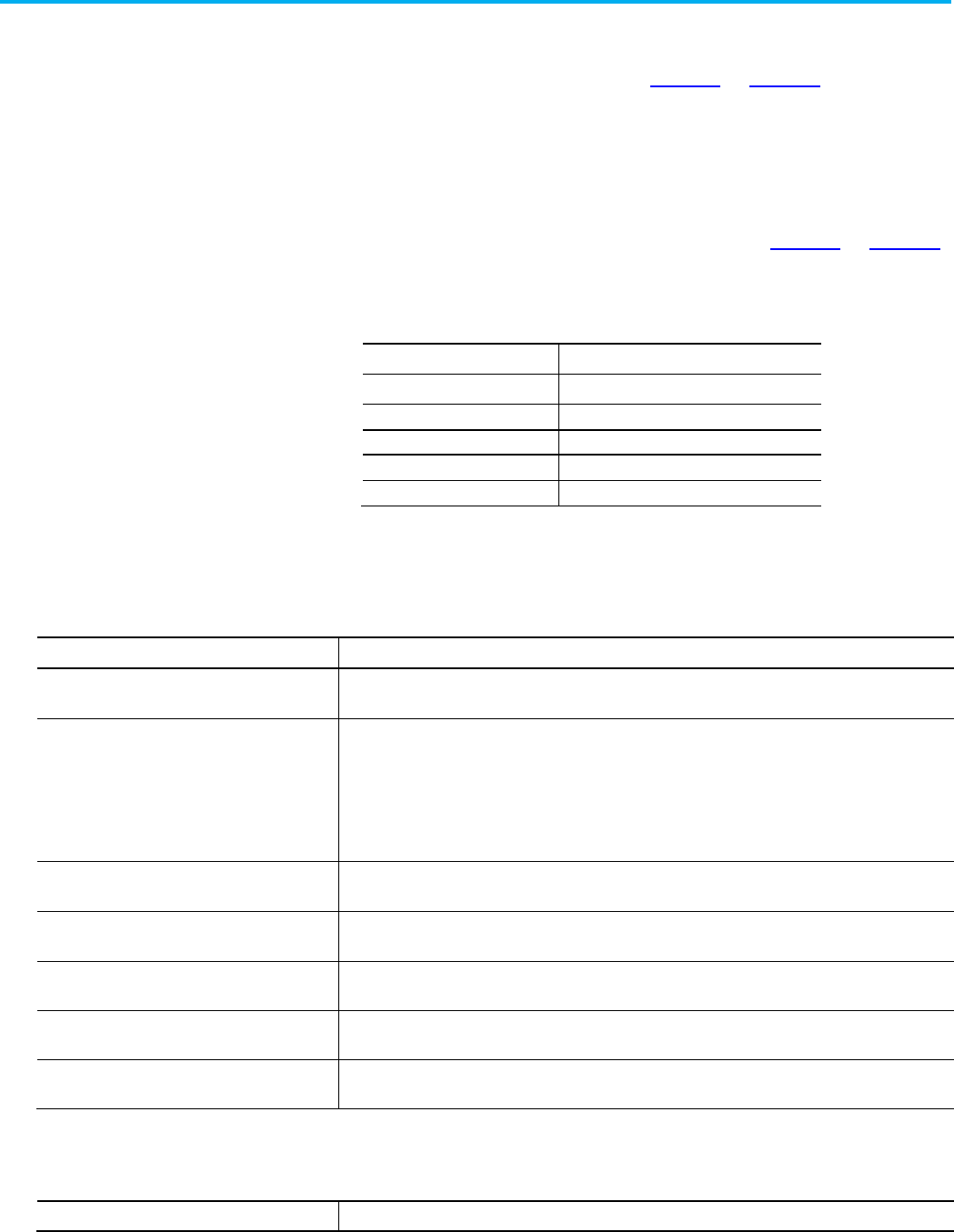
Appendix B Import/Export revision history
Publication 1756-RM014B-EN-P - November 2023 303
• CoarseUpdatePeriod and AutoTagUpdate parameters were added to
the MOTION_GROUP tag to support SERCOS. For reference, the
previous structure is described on page 267 on page 303.
• Earlier versions of the import/export feature supported one AXIS tag.
To support SERCOS, the import/export feature replaced AXIS with
four axis tags: AXIS_CONSUMED, AXIS_SERVO,
AXIS_SERVO_DRIVE, and AXIS_VIRTUAL. The previous AXIS tag is
incorporated into these new tags, but no longer exists as its own tag.
For reference, the AXIS structure is described on page 267 on page 303.
If you have a version 8.0 import/export file with AXIS tags that you
import into version 9.0 software, after changing the import/export
version line to 2.0), the AXIS tags convert to:
If the AXIS type is:
It Converts to:
Unused AXIS_SERVO
Position only
AXIS_SERVO
Servo AXIS_SERVO
Consumed AXIS_CONSUMED
Virtual AXIS_VIRTUAL
Refer to the MOTION_GROUP tag structure and descriptions.
Attribute
Description
Description Provide information about the tag.
Specify Description := "
text
"
Comment Provide information about a tag component.
Specify Comment<
specifier
> := "
text
"
Where the
specifier
is:
.
bitnumber
for a bit in the tag
[
element
]for an array element of the tag
.
membername
for a structure member of the tag
GroupType Specify the type of motion group, such as Independent.
Specify GroupType :=
text
CoarseUpdateMultiplier Specify the coarse update rate (5-320ms).
Specify CoarseUpdateMultiplier :=
value
ServoUpdatePeriod Specify the servo update period in milliseconds (any positive number)
Specify ServoUpdatePeriod :=
value
PhaseShift Specify the phase shift (0-65,535).
Specify PhaseShift :=
value
GeneralFaultType Specify whether an error generates a major fault or a non-major fault. Type
Major Fault
or
Non Major Fault
.
Specify GeneralFaultType :=
text
See the table for AXIS tag attributes (version 1.1).
Attribute
Description
MOTION_GROUP tag
structure (version 1.1)
AXIS tag structure (version
1.1)

Appendix B Import/Export revision history
304 Publication 1756-RM014B-EN-P - November 2023
Attribute
Description
Description
Provide information about the tag.
Specify Description := "
text
"
Comment Provide information about a tag component.
Specify Comment<
specifier
> := "
text
"
Where the
specifier
is:
.
bitnumber
for a bit in the tag
[
element
]for an array element of the tag
.
membername
for a structure member of the tag
MotionGroup Type the name of the associated motion group, or type
NA
.
Specify MotionGroup :=
text
MotionModule Type the name of the associated motion module, or type
NA
.
Specify MotionModule :=
text
AxisState Type
Axis-Ready
,
Direct Drive Control
,
Servo Control
,
Axis Faulted
, or
Axis Shutdown
.
Specify AxisState :=
text
PositionUnits Specify the type of units.
Specify PositionUnits :=
text
TimeUnits Type
Seconds
or
Minutes
.
Specify TimeUnits :=
text
InstructionSpeedUnits Type
Percentage
or
Engineering Units
.
Specify InstructionSpeedUnits :=
text
InstructionAccelDecelUnits Type
Percentage
or
Engineering Units
.
Specify InstructionAccelDecelUnits :=
text
InstructionMoveProfile Type
Trapezoidal
or
S-Curve
.
Specify InstructionMoveProfile :=
text
InstructionJogProfile Specify
Trapezoidal
or
S-Curve
.
Specify InstructionJogProfile :=
text
ConversionConstant Specify the conversion constant. Type a real number from 1.0...1.0e9.
Specify ConversionConstant :=
value
HomeMode Type
Passive
or
Active
.
Specify HomeMode :=
text
HomeSequenceType Type
Immediate Home
,
Home To Switch
,
Home To Marker Only
, or
Home To Switch With Marker
.
Specify HomeSequenceType :=
text
HomePosition Specify the home position (any positive number).
Specify HomePosition :=
value
HomeSpeed Specify the home speed (any positive number).
Specify HomeSpeed :=
value
HomeReturnSpeed Specify the home return speed (any positive number).
Specify HomeReturnSpeed :=
value
MaximumSpeed Specify the maximum speed (any positive number).
Specify MaximumSpeed :=
value
MaximumAcceleration Specify the maximum acceleration (any positive number).
Specify MaximumAcceleration :=
value
MaximumDeceleration Specify the maximum deceleration (any positive number).
Specify MaximumDeceleration :=
value
ProgrammedStopMode Type
Fast Stop
,
Fast Shutdown
, or
Hard Shutdown
.
Specify ProgrammedStopMode :=
text
AverageVelocityTimebase Specify the average velocity timebase (any positive number).
Specify AverageVelocityTimebase :=
value
ServoStatusUpdateBits Specify the servo status update bits. Type a hexadecimal number.
Specify ServoStatusUpdateBits := 16#
value

Appendix B Import/Export revision history
Publication 1756-RM014B-EN-P - November 2023 305
Attribute
Description
MotionConfigurationBits
Specify the motion configuration bits. Type a hexadecimal number.
Specify MotionConfigurationBits := 16#
value
AxisType
Type Unused, Position Only, Servo, Consumed, or Virtual.
Specify AxisType :=
text
PositionUnwind
Specify the unwind position (0-65,535).
Specify PositionUnwind :=
value
MaximumPositiveTravel
Specify the maximum positive travel (any positive number).
Specify MaximumPositiveTravel :=
value
MaximumNegativeTravel Specify the maximum negative travel (any positive number).
Specify MaximumNegativeTravel :=
value
PositionErrorTolerance Specify the position error tolerance (any positive number).
Specify PositionErrorTolerance :=
value
PositionLockTolerance Specify the position local tolerance (any positive number).
Specify PositionLockTolerance :=
value
PositionProportionalGain Specify position proportional gain (any positive number).
Specify PositionProportionalGain :=
value
PositionIntegralGain Specify the position integral gain (any positive number).
Specify PositionIntegralGain :=
value
VelocityFeedforwardGain Specify the velocity feedforward gain (any positive number).
Specify VelocityFeedforwardGain :=
value
AcclerationFeedforwardGain Specify the acceleration feedforward gain (any positive number).
Specify AccelerationFeedforwardGain :=
value
VelocityProportionalGain Specify the velocity proportional gain (any positive number).
Specify VelocityProportionalGain :=
value
VelocityIntegralGain Specify velocity integral gain (any positive number).
Specify VelocityIntegralGain :=
value
OutputFilterBandwidth Specify output filter bandwidth (any positive number).
Specify OutputFilterBandwidth :=
value
OutputScaling Specify the output scaling (any positive number).
Specify OutputScaling :=
value
OutputLimit Specify the output limit (any positive number).
Specify OutputLimit :=
value
OutputOffset Specify output offset (any positive number).
Specify OutputOffset :=
value
FrictionCompensation Specify friction compensation (any positive number).
Specify FrictionCompensation :=
value
SoftOvertravelFaultAction Type
Shutdown
,
Disable Drive
,
Stop Motion
, or
Status Only
.
Specify SoftOvertravelFaultAction :=
text
PositionErrorFaultAction Type
Shutdown
,
Disable Drive
,
Stop Motion
, or
Status Only
.
Specify PositionErrorFaultAction :=
text
EncoderLossFaultAction Type
Shutdown
,
Disable Drive
,
Stop Motion
, or
Status Only
.
Specify EncoderLossFaultAction :=
text
EncoderNoiseFaultAction Type
Shutdown
,
Disable Drive
,
Stop Motion
, or
Status Only
.
Specify EncoderNoiseFaultAction :=
text
DriveFaultAction Type
Shutdown
,
Disable Drive
,
Stop Motion
, or
Status Only
.
Specify DriveFaultAction :=
text
ServoConfigurationBits Specify the servo configuration bits. Type a hexadecimal number.
Specify ServoConfigurationBits := 16#
value
MotorEncoderTestIncrement Specify the motor encoder test increment (any positive number).
Specify MotorEncoderTestIncrement :=
value
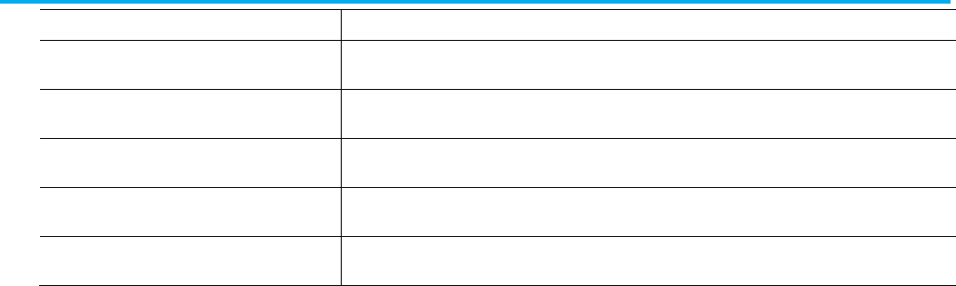
Appendix B Import/Export revision history
306 Publication 1756-RM014B-EN-P - November 2023
Attribute
Description
TuningTravelLimit
Specify the tuning travel limit (any positive number).
Specify TuningTravelLimit :=
value
TuningSpeed
Specify the tuning speed (any positive number).
Specify TuningSpeed :=
value
DampingFactor
Specify the damping factor (any positive number).
Specify DampingFactor :=
value
PositionServoBandwidth
Specify position servo bandwidth (any positive number).
Specify PositionServoBandwidth :=
value
TuningConfigurationBits Specify the tuning configuration bits. Type a hexadecimal number.
Specify TuningConfigurationBits := 16#
value
Version 1.1, major revision 1, minor revision 1, of the import/export feature
included with Logix Designer, version 8.0 includes these major
enhancements:
• Function block instructions and routines.
• ASCII instructions.
• Verification of all instruction attributes and parameters.
Import/Export version 1.1
Logix Designer version 8

Index
Publication 1756-RM014B-EN-P - November 2023 307
Index
A
action
attributes 195
L5K structure 195
L5X structure 195
Add-On Instruction
attributes 175
attributes in FBD 175
component 81
encoded data 90
guidelines 94
in a function block diagram routine 175
in FBD guidelines 94
L5K example 94
L5K source-protected example 93
L5K structure 82
L5K structure in FBD 175
L5X example 94
L5X source-protected example 92
L5X structure 81
L5X structure in FBD 175
local tag 89
local tag attributes 90
parameter 84, 85, 88
parameter attributes 87, 88
routines 83
source-protection 90
tag values 128
alarm analog tag
attributes 106
L5K example 130
L5K structure 106
L5X example 130
L5X structure 106
alarm digital tag
attributes 109
L5K example 130
L5K structure 109
L5X example 130
L5X structure 108
AlarmConfig
L5X structure 110
ALMMSG
record 268
analog alarm message
L5K structure 111
attachment
attributes 180
guidelines 180
L5K structure 180
L5X structure 179
attributes
action 195
Add-On Instruction 175
Add-On Instruction in FBD 175
alarm analog tag 106
alarm digital tag 109
attachment 180
block 173
branch 199
child programs 151
config objects 247
consumed tag 106
controller 51
controller config objects 247
coordinate system tag 124
datatype 64
datatype member 65
directed link 199
Encrypted content 92
Encryption Key 91
equipment phase 149
function 174
function block diagram routine 168
icon 172
iref 172
jsr 176
ladder logic routine 157
leg 199
local tag 90
message tag 111
module 70
module connection 75
motion group tag 126
ocon 172
oref 172
parameter 87, 88
parameter connections 231
pen 239
produced tag 105
program 148
quick watch list 243

Index
308 Publication 1756-RM014B-EN-P - November 2023
ret 178
rung 159
safety controller 54, 75
safety module 73
safety tag 127
sbr 177
sbrret 197
sequential function chart routine 190
sheet 169
step 193
stop 198
structured text routine 210
tag 104
task 228
text box 179
TrackingGroups 82, 104, 157, 168, 190,
210
transition 196
trend 235
watch tag 243
wire 178
axis tag
L5K structure 112
L5X structure 112
B
backward compatibility 277
block
attributes 173
guidelines 174
L5K structure 173
L5X structure 173
boolean values
L5X format 40
branch
attributes 199
L5K structure 159
L5X structure 159
C
child programs
attributes 151
components 150
guidelines 151
L5K example 153
L5K structure 150
L5X example 153
L5X structure 151
COMMENT
record 267
comments 28, 30, 46
CSV format 265
internal L5K file 46
internal L5X file 46
TXT Unicode format 265
complete import/export 21, 22, 25, 26
components
Add-On Instruction 81
basic L5K format 44
basic L5X format 36
child programs 150
config 247
datatype 63
descriptions in L5K 46
descriptions in L5X 46
display style in L5K 46
display style in L5X 40
function block diagram routine 167
ladder logic routine 157
module 69
parameter connections 231
program 147
quick watch list 243
sequential function chart routine 189
structured text routine 209
tag 101
task 227
trend 235
condition
L5K structure 197
L5X structure 197
config
component 247
L5K examples 247
L5X examples 247
config objects
attributes 247
L5K structure 247
L5X structure 247
consumed tag
attributes 106
controller
attributes 51
guidelines 54
L5K example 54
L5K safety example 54
L5K structure 50
L5X example 54
L5X safety example 54

Index
Publication 1756-RM014B-EN-P - November 2023 309
L5X structure 49
safety attributes 54
controller config objects 247
attributes 247
L5K examples 247
L5X examples 247
coordinate system tag
attributes 124
L5K structure 124
L5X structure 124
CSV
ALMMSG 268
comment record 267
exporting 28
importing 30
TAG 265
CSV format 265, 275
examples 268
D
data formats
L5X format 40
datatype
attributes 64
bit members 65
component 63
guidelines 67
L5K example 67
L5K structure 63
L5X example 67
L5X structure 63
member attributes 65
members 64
datatype member
attributes 65
bit members 65
L5K structure 64
L5X structure 64
descriptions
L5K format 46
L5X format 46
directed link
attributes 199
guidelines 200
L5K structure 199
L5X structure 199
display style
L5K format 46
L5X format 40
E
encoded data
L5K example 93, 153
L5K structure 90
L5X example 92, 153
L5X structure 90
equipment phase
attributes 149
L5K example 153
L5X example 153
examples
CSV files 268
L5K ADD_ON_INSTRUCTION_DEFINITION
94
L5K ALARM_ANALOG tag 130
L5K ALARM_DIGITAL tag 130
L5K CHILD_PROGRAMS 153
L5K CONFIG 247
L5K CONTROLLER 54
L5K DATATYPE 67
L5K ENCODED_DATA 93, 153
L5K equipment phase PROGRAM 153
L5K FBD_ROUTINE 180
L5K LOGIC 170, 191, 211
L5K MODULE 76
L5K PROGRAM 153
L5K QUICK_WATCH_LIST 243
L5K ROUTINE 160
L5K safety CONTROLLER 54
L5K safety partner MODULE 76
L5K safety TAG 130
L5K safety TASK 228
L5K SFC_ROUTINE 180
L5K source-protected Add-On Instruction
93
L5K source-protected routine 153
L5K ST_ROUTINE 211
L5K TAG 130
L5K TASK 228
L5K TREND 239
L5X AddOnInstructionDefinition 94
L5X alarm analog Tag 130
L5X alarm digital Tag 130
L5X ChildPrograms 153
L5X Controller 54
L5X controller config objects 247
L5X DataType 67
L5X EncodedData 92, 153
L5X equipment phase Program 153
L5X FBDContent 170

Index
310 Publication 1756-RM014B-EN-P - November 2023
L5X function block diagram Routine
180
L5X Module 76
L5X Program 153
L5X QuickWatchList 243
L5X Routine 159
L5X safety Controller 54
L5X safety partner Module 76
L5X safety Tag 130
L5X sequential function chart Routine
180
L5X SFCContent 191
L5X source-protected Add-On Instruction
92
L5X source-protected routine 153
L5X STContent 211
L5X structured text Routine 211
L5X Tag 130
L5X Task 228
L5X Trend 239
parameter connections 232
TXT Unicode files 268
Excel 275
exporting
comments 28
complete project 21, 25
CSV format 28
L5K format 21
L5X format 25
project 21, 25
tags 28
text boxes 28
TXT format 28
F
format
CSV 265
TXT Unicode 265
function block diagram
instructions 184
neutral text 184
function block diagram routine
Add-On Instruction attributes 175
attachment attributes 180
attributes 168
component 167
FBDContent 170
jsr attributes 176
L5K example 170, 180
L5K online edits example 170
L5K sheet structure 169
L5K structure 167
L5X example 170, 180
L5X online edits example 170
L5X sheet structure 168
L5X structure 167
LOGIC 170
online edits 170
ret attributes 178
sbr attributes 177
sheet attributes 169
sheet guidelines 170
text box attributes 179
wire attributes 178
function block routine
block attributes 173
icon attributes 172
iref attributes 172
ocon attributes 172
oref attributes 172
functions 174
G
guidelines
Add-On Instruction 94
Add-On Instruction in FBD 94
attachment 180
block 174
child programs 151
controller 54
datatype 67
directed link 200
icon 173
iref 172
jsr 177
module 76
ocon 173
oref 172
parameter connections 231
program 153
ret 178
rung 159
sbr 177
sheet 170
tag 130
task 228
text box 200
trend 239
wire 179

Index
Publication 1756-RM014B-EN-P - November 2023 311
H
history, import/export feature 277
I
icon
attributes 172
guidelines 173
L5K structure 172
L5X structure 172
importing
comments 30
complete project 22, 26
CSV format 30
L5K format 22
L5X format 26
project 22, 26
tags 30
text boxes 30
TXT format 30
initial values 128
Add-On Instruction 128
L5K structure 128
L5X structure 128
instructions
function block diagram 184
ladder logic 161
structured text 213
internal file comments 46
iref
attributes 172
guidelines 172
L5K structure 172
L5X structure 171
J
jsr
attributes 176
guidelines 177
L5K structure 176
L5X structure 176
L
L5K
exporting 21
file conventions 45
file structure 44
importing 22
internal file comments 46
L5K structure
action 195
Add-On Instruction 82
Add-On Instruction in FBD 175
alarm analog tag 106
alarm digital tag 109
analog alarm message 111
attachment 180
axis tag 112
block 173
branch 159
child programs 150
condition 197
config objects 247
controller 50
coordinate system tag 124
datatype 63
datatype member 64
directed link 199
encoded data 90
function block diagram routine 167
icon 172
iref 172
jsr 176
ladder logic routine 157
limithigh 194
limitlow 194
local tag 89
message tag 111
module 69
module connection 74
motion group tag 126
ocon 172
oref 172
parameter 85, 88
parameter connections 231
pen 238
preset 194
program 147
quick watch list 243
ret 177
rung 158
rung branch 159
safety tag 127
sbr 177
sbrret 197
sequential function chart routine 189
sheet 169
source-protected Add-On Instruction
90
source-protected routine 90

Index
312 Publication 1756-RM014B-EN-P - November 2023
step 193
stop 198
structured text routine 209
tag 102
tag initial values 128
task 227
text box 179
transition 196
trend 235
wire 178
L5X
boolean attribute values 40
data formats 40
exporting 25
file conventions 39
file structure 36
importing 26
internal file comments 46
L5X structure
action 195
Add-On Instruction 81
Add-On Instruction in FBD 175
alarm analog tag 106
alarm digital tag 108
AlarmConfig 110
attachment 179
axis tag 112
block 173
branch 159
child programs 151
condition 197
config objects 247
controller 49
coordinate system tag 124
datatype 63
datatype member 64
directed link 199
encoded data 90
function block diagram routine 167
icon 172
iref 171
jsr 176
ladder logic routine 157
limithigh 194
limitlow 195
local tag 89
message tag 111
module 69
module connection 73
motion group tag 126
ocon 172
oref 171
parameter 84, 88
parameter connections 231
pen 238
preset 194
program 147
quick watch list 243
ret 177
rung 158
rung branch 159
safety tag 127
sbr 177
sbrret 197
sequential function chart routine 189
sheet 168
source-protected Add-On Instruction
90
source-protected routine 90
step 192
stop 198
structured text routine 209
tag 101
tag initial values 128
task 227
text box 179
transition 196
trend 235
wire 178
ladder logic
instructions 161
neutral text 161
rung attributes 159
ladder logic routine
attributes 157
component 157
L5K example 160
L5K rung branch structure 159
L5K rung structure 158
L5K structure 157
L5X example 159
L5X rung branch structure 159
L5X rung structure 158
L5X structure 157
rung guidelines 159
language switching 46
leg
attributes 199
limithigh
L5K structure 194
L5X structure 194

Index
Publication 1756-RM014B-EN-P - November 2023 313
limitlow
L5K structure 194
L5X structure 195
local tag
attributes 90
L5K structure 89
L5X structure 89
M
message tag
attributes 111
L5K structure 111
L5X structure 111
Microsoft Excel 275
module
attributes 70
component 69
guidelines 76
L5K example 76
L5K safety partner example 76
L5K structure 69
L5X example 76
L5X safety example 76
L5X structure 69
safety attributes 73
module connection
attributes 75
L5K structure 74
L5X structure 73
safety attributes 75
motion group tag
attributes 126
L5K structure 126
L5X structure 126
N
neutral text
function block diagram 184
ladder logic 161
structured text 213
O
objects 247
ocon
attributes 172
guidelines 173
L5K structure 172
L5X structure 172
online edits 170, 191, 211
oref
attributes 172
guidelines 172
L5K structure 172
L5X structure 171
P
parameter
attributes 87, 88
L5K structure 85, 88
L5X structure 84, 88
parameter connections
attributes 231
components 231
guidelines 231
L5K example 232
L5K structure 231
L5X example 232
L5X structure 231
pen
attributes 239
L5K structure 238
L5X structure 238
preset
L5K structure 194
L5X structure 194
produced tag
attributes 105
program
attributes 148
component 147
equipment phase attributes 149
guidelines 153
L5K equipment phase example 153
L5K example 153
L5K structure 147
L5X equipment phase example 153
L5X example 153
L5X structure 147
routine encoded data 90
source-protected routine 90
projects 21, 22, 25, 26
Q
quick watch list
attributes 243
component 243
L5K example 243
L5K structure 243

Index
314 Publication 1756-RM014B-EN-P - November 2023
L5X example 243
L5X structure 243
watch tag attributes 243
R
RCOMMENT 265
record 267
Remark 265
ret
attributes 178
guidelines 178
L5K structure 177
L5X structure 177
routine
component 157, 167, 189, 209
encoded data 90
in Add-On Instruction 83
L5K example 160, 180
L5K source-protected example 153
L5X example 159, 180, 211
L5X source-protected example 153
source-protection 90
rung
attributes 159
guidelines 159
L5K structure 158
L5X structure 158
rung branch
L5K structure 159
L5X structure 159
S
safety controller
attributes 54, 75
L5K example 54
L5K module example 76
L5K safety example 228
L5K tag example 130
L5X example 54
L5X module example 76
L5X tag example 130
module attributes 73
safety partner module
L5K example 76
L5X example 76
safety tag
attributes 127
L5K example 130
L5K structure 127
L5X example 130
L5X structure 127
sbr
attributes 177
guidelines 177
L5K structure 177
L5X structure 177
sbrret
attributes 197
L5K structure 197
L5X structure 197
sequential function block routine
L5K example 191
L5K online edits example 191
sequential function chart
attachment attributes 180
attachment guidelines 180
directed link guidelines 200
text box attributes 179
text box guidelines 200
sequential function chart routine
action attributes 195
attributes 190
branch attributes 199
component 189
directed link attributes 199
L5K action structure 195
L5K attachment structure 180
L5K branch structure 159
L5K condition structure 197
L5K directed link structure 199
L5K example 180
L5K limithigh structure 194
L5K limitlow structure 194
L5K preset structure 194
L5K sbrret structure 197
L5K step structure 193
L5K stop structure 198
L5K structure 189
L5K text box structure 179
L5K transition structure 196
L5X action structure 195
L5X attachment structure 179
L5X branch structure 159
L5X condition structure 197
L5X directed link structure 199
L5X example 180, 191
L5X limithigh structure 194
L5X limitlow structure 195
L5X online edits example 191

Index
Publication 1756-RM014B-EN-P - November 2023 315
L5X preset structure 194
L5X sbrret structure 197
L5X step structure 192
L5X stop structure 198
L5X structure 189
L5X text box structure 179
L5X transition structure 196
leg attributes 199
LOGIC 191
online edits 191
sbrret attributes 197
SFCContent 191
step attributes 193
stop attributes 198
transition attributes 196
sheet
attributes 169
guidelines 170
L5K structure 169
L5X structure 168
step
attributes 193
L5K structure 193
L5X structure 192
stop
attributes 198
L5K structure 198
L5X structure 198
structured text
instructions 213
neutral text 213
structured text routine
attributes 210
component 209
L5K example 211
L5K online edits example 211
L5K structure 209
L5X example 211
L5X online edits example 211
L5X structure 209
logic 210, 211
online edits 211
STContent 211
T
tag 265
alarm analog attributes 106
alarm digital attributes 109
attributes 104
component 101
consumed attributes 106
coordinate system attributes 124
guidelines 130
initial values 128
L5K alarm analog example 130
L5K alarm analog structure 106
L5K alarm digital example 130
L5K alarm digital structure 109
L5K axis structure 112
L5K coordinate system structure 124
L5K example 130
L5K initial values structure 128
L5K message structure 111
L5K motion group structure 126
L5K safety example 130
L5K safety structure 127
L5K structure 102
L5X alarm analog example 130
L5X alarm analog structure 106
L5X alarm digital example 130
L5X alarm digital structure 108
L5X axis structure 112
L5X coordinate system structure 124
L5X example 130
L5X initial values structure 128
L5X message structure 111
L5X motion group structure 126
L5X safety example 130
L5X safety structure 127
L5X structure 101
motion group attributes 126
produced attributes 105
record 265
safety attributes 127
tags 28, 30
task
attributes 228
component 227
guidelines 228
L5K example 228
L5K structure 227
L5X example 228
L5X structure 227
text box
attributes 179
guidelines 200
L5K structure 179
L5X structure 179
text boxes 28, 30
text file 21
TEXTBOX 265

Index
316 Publication 1756-RM014B-EN-P - November 2023
TEXTBOX record 267
TrackingGroup 82, 104, 157, 190, 210
transition
attributes 196
L5K structure 196
L5X structure 196
trend
attributes 235
component 235
guidelines 239
L5K example 239
L5K pen structure 238
L5K structure 235
L5X example 239
L5X pen structure 238
L5X structure 235
pen attributes 239
TXT
ALMMSG 268
comment record 267
exporting 28
format 265
importing 30
TAG 265
TXT Unicode format 265
examples 268
U
Unicode TXT format 265
W
watch list 243
watch tag 243
wire
attributes 178
guidelines 179
L5K structure 178
L5X structure 178
X
XML file 25
Allen-Bradley, expanding human possibility, Logix, Rockwell Automation, and Rockwell Software are trademarks of Rockwell Automation, Inc.
EtherNet/IP is a trademark of ODVA, Inc.
Trademarks not belonging to Rockwell Automation are property of their respective companies.
Rockwell Otomayson Ticaret A.Ş. Kar Plaza İş Merkezi E Blok Kat:6 34752, İçerenkÖy, İstanbul, Tel: +90 (216) 5698400 EEE YÖnetmeliğine Uygundur
Publication 1756-RM014B-EN-P - November 2023
Supersedes Publication 1756-RM014A-EN-P - March 2022 Copyright © 2023 Rockwell Automation Technologies, Inc. All Rights Reserved. Printed in the U.S.A.
Rockwell Automation support
Use these resources to access support information.
Technical Support Center
Find help with how-to videos, FAQs, chat, user forums, and product notification
updates.
rok.auto/support
Knowledgebase
Access Knowledgebase articles.
rok.auto/knowledgebase
Local Technical Support Phone Numbers
Locate the telephone number for your country. rok.auto/phonesupport
Literature Library
Find installation instructions, manuals, brochures, and technical data publications.
rok.auto/literature
Product Compatibility and Download Center
(PCDC)
Get help determining how products interact, check features and capabilities, and
find associated firmware.
rok.auto/pcdc
Documentation feedback
Your comments help us serve your documentation needs better. If you have any suggestions on how to improve our content, complete the form at
rok.auto/docfeedback.
Waste Electrical and Electronic Equipment (WEEE)
Note: At the end of life, this equipment should be collected separately from any unsorted municipal
waste.
Rockwell Automation maintains current environmental information on its website at rok.auto/pec.
